
User Documentation

4 Module descriptions | Digital input and output modules IP67, PROFIBUS, 60mm, metal housing
182484950000/00/03.2016 Manual UR67-PROIFBUS
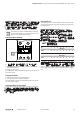
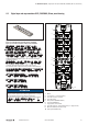
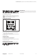
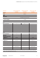
Diagnosis and status LED
LED Indicator Meaning
Module related LED
ACT yellow Data exchange with PROFIBUS master
BF
red Bus error, no communication
off No error
DIA
red Collective message for peripheral errors
off No error message exsisting
U
S
green Sensor/system supply 24VDC ± 25%
red Sensor/system supply U
S
<18V or U
S
>30V
off No sensor/system supply
U
L
green Actuator supply 24VDC ± 25%
red Actuator supply U
L
<18V or U
L
>30V
off No actuator supply
Channel related LED
1 ... 8 A
yellow Channel A „on“
red
Peripheral error (actuator undervoltage, sensor or actuator
short circuit)
off Not connected, status „off“, no error
1 ... 8 B
white Channel B „on“
red
Peripheral error (actuator undervoltage, actuator short
circuit)
off Not connected, status „off“, no error
LED indicators, error messages see chapter9
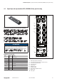
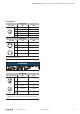
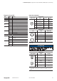
Connection assignments
I/O connections
M12, A-coded 8DIDO 16DI 16DO
1
3
5
4
2
1
X1...X4: 24V
X5...X8: n. c.
24V n. c.
2
X1...X4: In B
X5...X8: Out B
In B Out B
3 GND GND GND
4
X1...X4: In A
X5...X8: Out A
In A Out A
5 FE FE FE
Voltage supply
7/8" 16DI 8DIDO, 16DO
24
5
3
1
2 4
5
3
1
1
Internally bridged with
contact5
GND (0V) DC
2 GND (0V) DC GND (0V) DC
3 FE FE
4 24VDC ± 25% 24VDC ± 25%
5
Internally bridged with
contact1
24VDC ± 25%
Power supply units for the system/sensor supply and the actuator supply must conform
to SELV or PELV.
ATTENTION
Product can be destroyed!
▶ Please do never position the power supply (24VDC) at
the signal or data lines (pin 1 to pin4).
PROFIBUS-DP
M12, B-coded Signal Function
2
4
5
3
1
Male IN
2
4
5
3
1
Female OUT
1 VP
1)
+5V
2 RxD/TxD- N Channel A
3 GND (0V)
1)
GND
4 RxD/TxD- P Channel B
5 n.c. FE
1) Internal signals that can be used to supply a terminating resistor (OrderNo.
1784770000). They may never be wired up or forwarded to other partici-
pants.