
User Documentation


6 Earthing and shielding | Shielding of cables
362484950000/00/03.2016 Manual UR67-PROIFBUS
Only when a cable shield is connected to the local refer-
ence potential on both sides is it possible to achieve optimal
shielding against electric and magnetic elds. Exceptions
are possible, for example, with high-impedance, symmetrical
or analogue signal cables. If a shield is attached on only one
side, this merely achieves an isolation against electric elds.
ATTENTION
Material damage!
Requirements for effective shielding design:
– The shield connection to the shield bus should be low
impedance
– The shield must be connected directly at its entrance
into the system
– Keep cable ends as short as possible
– Do not use cable shields for equipotential bonding
When connecting a data cable using a sub-D connector, the
connection must be made through the connector's shield
collar and never through pin 1.
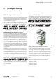
The data cable's shield must be attached to the shield bus
with the insulation stripped away. The shield is to be con-
nected and attached with clamping brackets or similar metal
xing devices. The shield bus must be connected to the refer-
ence potential surface through a low impedance (e.g.fasten-
ing point with a separation of 10 to 20cm). The brackets
must surround and make contact with a large part of the
shield.
Isolation of the cable shield should be avoided. Instead, it
should be routed into the system (for example, the switch
cabinet) up to the interface connection.
ATTENTION
Shielding of eld bus cables
When shielding eld-bus cables, the installation guidelines
for the respective eld buses must be observed. (See the
websites of the eld bus organisations.)
Material damage!
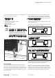
If it is only possible to have a one-sided shield connection
for reasons specic to the circuit or equipment, the second
side of the cable shield can be routed to the local reference
potential via a capacitor (with short connections). To pre-
vent disruptive discharges when interference pulses occur,
a varistor or a resistor can also be wired in parallel to the
capacitor.
As an alternative, a doubled version (galvanically isolated)
can be used, whereby the inner shield is connected on one
side and the outside shield is connected on both sides.
Equipotential bonding
If system components are positioned separately from each
other, potential differences may arise, provided that:
– Power is provided from different sources
– The earthing is implemented at different system parts,
despite the cable shields being connected at both sides
A voltage equalising cable must be used for equipotential
bonding.
WARNING
Possible danger to life!
The shield must not be used for equipotential
bonding!
The following features are essential for a voltage equalising
cable:
– In the case of cable shields on both ends, the impedance
of the equalising cable must be considerably smaller than
that of the shield connection (maximum 10 % of its
impedance)
– When the length of the equalising cable is less than
200m, its cross-section must be at least 16 mm
2
If the
cable is greater than 200m in length, a cross-section of
at least 25 mm
2
is necessary.
– Large-surface connection with the PE conductor or the
earthing and corrosion protection are requirements for
long-term safe operation
– They must be made of copper or galvanised steel
– In order to keep the enclosed area as small as possible,
the equalising cable and signal cable must be routed as
close to each other as possible
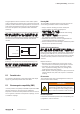
Wiring of inductances
In case of inductive loads we recommend a suppressor circuit directly
on the load. The ground (PE/FE) must be positioned star-shaped
according to the standards.