
User Documentation


5 Installation
WARNING
Dangerous contact voltage!
▶ Carry out assembly and wiring work on
the u-remote station only when the power
supply is disconnected.
▶ Make sure that the place of installation
(switch cabinet etc.) has been discon-
nected from the power supply!
5.1 Preparations for assembly
Make sure that the permitted environmental conditions for
installation and operation are observed (see technical data).
The installation ground must be even and plain.
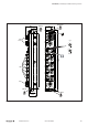
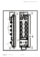
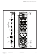
Installation position and dimensions
The modules with plastic housing (A, B) can be installed
either laying at or lateral upright. The modules with metal
housing (C) must be installed laying plain. You will nd the in-
stallation dimensions as well as the tightening torques in the
mounting drawings on the following pages.
Unpacking the delivery
▶ Please check the delivery for completeness and transport
damage.
▶ Please report any transport damage immediately to the
respective transport company.
ATTENTION
The product can be destroyed by elec-
trostatic discharge!
The components in the u-remote series can
be destroyed by electrostatic discharge.
▶ Please make sure that personnel and work
equipment are adequately earthed!
▶ Unpack all parts.
▶ Dispose of all packaging in accordance with the local dis-
posal guidelines. The cardboard packaging can be sent
for paper recycling.
5.2 Assembling the module and earthing con-
nection
▶ Drill the assembling holes (drilling dimensions see mount-
ing drawings on the following pages).
▶ Adjust each module using at least two screws with grom-
mets (according to DIN125).
▶ Please regard the noted screw dimensions and tightening
torques.
Element Tightening torque
M8 plug connector 0.3Nm
M8 protection cap 0.3Nm
M12 plug connector 0.6Nm
M12 protection cap 0.6Nm
Lock of the clear cover (rotary switches) 0.5Nm
The module must be earthed in order to discharge distur-
bance currances and for the EMC stability.
▶ Connect the earthing clamp (A, B) or the earthing connec-
tor (C) with ground using a low impedant connection.
In case the mounting ground is earthed you can realise the
connection directly using a mounting screw (not possible
with lateral mounting). If the mounting ground is not earthed
or with lateral mounting please use a earthing strap or an ap-
propriate line!
5 Installation | Preparations for assembly
272484950000/00/03.2016 Manual UR67-PROIFBUS