
User Documentation


5 Detailed descriptions of safe modules | Digital input module UR20-8DI-PN-FSPS, UR20-8DI-PN-FSPS-V2
47u-remote IP20 modules for functional safety manual 1484600000/07/11.2020
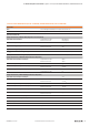
5.6 Digital input module UR20-8DI-PN-FSPS, UR20-8DI-PN-FSPS-V2
Digital input module UR20-8DI-PN-FSPS (Best.-Nr. 1335070000), UR20-8DI-PN-FSPS-V2
(Best.-Nr.2464590000)
The UR20-8DI-PN-FSPS or UR20-8DI-PN-FSPS-V2 digital in-
put module is a safe I/O module for the PROFIsafe protocol.
The module can detect up to 8binary control signals. Two
sensors can be connected to each connector using a 2-wire,
3-wire or 4-wire connection. In the event that the available
supply current of 0.8A per plug will not sufce, the sensor
supply must be realised using the auxiliary outputs of an-
other module (e.g. potential distribution module) within the
same power segment.
Astatus LED is assigned to each channel. The module elec-
tronics supply the connected sensors with power from the
input current path (I
IN
)
A test pulse check of the inputs can be parameterised as a
cross-circuit detection between input singal and supply volt-
age, between different input signals or other signals. Thus an
input gets active only when the signal of the dedicated aux-
iliary output is pending. The test pulses must be disabled if a
safety relay with OSSD outputs generating own test pulses is
connected.
1
2
3
4
2
1
3
4
1
2
3
4
2
4
3
1
2
4
3
1
1
2
3
4
2
1
3
4
1
2
3
4
2
4
3
1
2
4
3
1
DI 0 (PN)
AUX-O 0
AUX-O 1
DI 1 (P)
DI 2 (PN)
AUX-O 2
AUX-O 3
AUX-O 0
AUX-O 1
AUX-O 2
AUX-O 3
DI 3 (P)
DI 4 (PN)
AUX-O 4
AUX-O 5
DI 5 (P)
DI 6 (PN)
AUX-O 6
AUX-O 7
DI 7 (P)
8DI·PN
DI 0 (PN)
GND
24 V DC
GND
24 V DC
DI 1 (P)
DI 2 (PN)
DI 3 (P)
DI 4 (PN)
AUX-O 4
AUX-O 5
DI 5 (P)
DI 6 (PN)
AUX-O 6
AUX-O 7
DI 7 (P)
8DI·PN
Safety relay
with OSSD
outputs
1
Safety relay
with OSSD
outputs
2
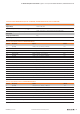
Connection diagram UR20-8DI-PN-FSPS , UR20-8DI-PN-FSPS-V2
A safety sensor that is being connected in a dual chan-
nel mode (safety architecture of category 4 acc. to
DINENISO13849) must allocate the PN and the P-input of
one connector.