
User Documentation
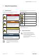


1 About this documentation 3
1.1 Symbols and notes 3
1.2 Complete documentation 3
2 Safety 5
2.1 General safety notice 5
2.2 Intended use 6
2.3 Use in a potentially explosive atmosphere 6
2.4 Notes on functional safety 6
2.5 Legal notice 7
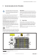
3 System description of safe I/O modules 9
3.1 Sample design 9
3.2 Transition diagramm 10
3.3 Current-/voltage characteristics of the fail safe digital inputs 10
3.4 Registration of safe I/O modules on the safety control 11
3.5 Safety address 11
3.6 External circuitry of a PN/P output pair 12
3.7 Operating with and without own test pulses 12
3.8 Processing time 14
4 System description of safe power-feed modules 15
4.1 Sample design 16
4.2 Transition diagramm 17
4.3 Modules switchable by PF-O-xDI-SIL 18
4.4 Conguration 18
4.5 Switch-off delay time 18
4.6 Operation with and without test pulses 19
5 Detailed descriptions of safe modules 21
5.1 General technical data 21
5.2 Data width dependent on the coupler used 22
5.3 Digital in- and output module UR20-4DI-4DO-PN-FSOE,
UR20-4DI-4DO-PN-FSOE-V2 24
5.4 Digital input module UR20-8DI-PN-FSOE, UR20-8DI-PN-FSOE-V2 32
5.5 Digital in- and output module UR20-4DI-4DO-PN-FSPS,
UR20-4DI-4DO-PN-FSPS-V2 39
5.6 Digital input module UR20-8DI-PN-FSPS, UR20-8DI-PN-FSPS-V2 47
5.7 Safe power-feed module UR20-PF-O-1DI-SIL 54
5.8 Safe power-feed module UR20-PF-O-2DI-SIL 59
5.9 Safe power-feed module UR20-PF-O-2DI-DELAY-SIL 64
6 Installation and replacement 71
7 Example applications 73
7.1 Example applications for safe I/O modules 73
7.2 Dual-channel emergency stop monitoring 76
7.3 Dual-channel light curtain monitoring (AOPD type 4)
and emergency stop monitoring 77
7.4 Dual-channel emergency stop and cable-pull switch monitoring 78
7.5 Dual-channel safety door monitoring with automatic reset
and emergency stop 79
7.6 Safety mat 80
7.7 Dual-channel two-hand monitoring with automatic start 81
7.8 Dual-channel safety door monitoring with magnetic switch,
automatic reset and emergency stop 82
7.9 Dual-channel safety door monitoring, spring-operated interlock
with manual reset and emergencystop 83
7.10 Dual-channel safety door monitoring, magnetically operated interlock
with manual reset and emergency stop 84
7.11 Dual-channel safety door monitoring with proximity sensors,
automatic reset and emergency stop 85
7.12 Dual-channel safety door monitoring, spring-operated interlock,
controlled shutdown with manual reset and emergency stop 86
7.13 Dual-channel safety door monitoring with automatic reset
and controlled shutdown and emergency stop 87
7.14 Cascading 88
8 LED displays and troubleshooting 89
8.1 Safe I/O modules 89
8.2 Safe power-feed modules 91
9 Accessories and replacement parts 93
9.1 Accessories 93
9.2 Replacement parts 94
ANNEX
Checklist for the use of u-remote safety modules A-2
EC Declaration of Conformity A-5
TÜV Certicates A-27
Content
2 1484600000/07/11.2020u-remote IP20 modules for functional safety manual
Manufacturer
Weidmüller Interface GmbH & Co. KG
Klingenbergstraße 16
32758 Detmold, Germany
T +49 5231 14-0
F +49 5231 14-292083
www.weidmueller.com
Document No. 1484600000
Revision 07/November 2020