
User Documentation


88 1484600000/07/11.2020u-remote IP20 modules for functional safety manual
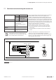
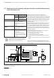
7.14 Cascading
Achievable safety rating Category 4 ENISO13849-1
PLe ENISO13849-1
SIL 3 EN62061/61508
Notes A shielded cable installation is neccessary
if the safely switched-off line (24V Safe
at 4.2) runs outside the switch cabinet.
All examples shown are proposals without war-
ranty. In any case the operator has to perform a
safety review of the entire site.
1.1
1.2
1.3
1.4
3.1
3.2
3.3
3.4
4.1
4.2
4.3
4.4
1.1
1.2
1.3
1.4
2.1
2.2
2.3
2.4
3.1
3.2
3.3
3.4
4.1
4.2
4.3
4.4
1.1
1.2
1.3
1.4
3.1
3.2
3.3
3.4
4.1
4.2
4.3
4.4
1.1
1.2
1.3
1.4
2.1
2.2
2.3
2.4
3.1
3.2
3.3
3.4
4.1
4.2
4.3
4.4
UR20-PF-O-xDI-SIL UR20-4DO-P
K4
K3
UR20-PF-OxDI--SIL UR20-4DO-P
K2
K1
K4K3
K2K1
S4S5
S1
S3
S2
L+(+24V)
M (0V)
Emergency stop
Robot cell Conveyor belt
Reset Reset
Safety door
(closed)
Emergency stopCable-pull switch,
latching
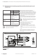
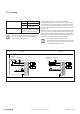
Example application for cascading
The following shows the cascading of PF-O-xDI-SIL
modules. When the safety door for the robot cell is opened
in the example, the conveyor belt is also switched off at the
same time. In contrast, switching off the conveyor belt, e.g.
with the cable-pull switch, does not automatically switch off
the robot cell.
Multiple cascade levels and also multiple PF-O-xDI-SIL mod-
ules can be used on a single level. Be aware that the trigger-
ing of an PF-O-xDI-SIL module immediately switches off the
24V supply of all subsequent safe power-feed modules. A
delay of these modules is then no longer effective.
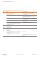
Please regard during commissioning:
After switching on the u-remote station the man-
ual start has to be operated once for each single
cascaded PF-O-xDI-SIL module.