
User Documentation


7 Example applications | Dual-channel safety door monitoring, spring-operated interlock with manual reset and emergencystop
83u-remote IP20 modules for functional safety manual 1484600000/07/11.2020
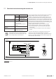
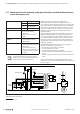
7.9 Dual-channel safety door monitoring, spring-operated interlock with manual reset and emergen-
cystop
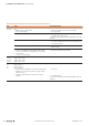
Achievable safety rating Category 3 ENISO13849-1
PLe ENISO13849-1
SIL 3 EN62061/61508
Stop category 0 EN60204-1
Features – Dual-channel monitoring
– Cross-connection detection
– Manual reset
– Monitoring of external contactors
(EDM)
Safety sensor/operating
mechanism
– Emergency stop button
– Position switch with interlock
– Zero-speed monitor
– Manual unlocking
Notes Exclusion of the fault “Interruption or
releasing of the activator, error in the
safety interlock”
All examples shown are proposals without
warranty. In any case the operator has to per-
form a safety review of the entire site.
1.1
1.2
1.3
1.4
3.1
3.2
3.3
3.4
4.1
4.2
4.3
4.4
1.1
1.2
1.3
1.4
2.1
2.2
2.3
2.4
3.1
3.2
3.3
3.4
4.1
4.2
4.3
4.4
M
UR20-PF-O-xDI-SIL UR20-4DO-P
K4
K3
K4K3Reset
S1
S2S4
S5 S3
L+(+24 V)
M (0 V)
K4
K3
Emergency stop
Safety door
(closed)
Zero-speed monitoring
Unlocking mechanism
Example application for dual-channel emergency stop monitoring
1)
Switchable modules see section4.3
When the emergency stop button is pushed, the
PF-O-xDI-SIL switches off the 24V supply for the mod-
ules
1)
within the safety segment and thus also contactors K3
and K4. The failure of a switching element in the emergency
stop button or the safety door contact as well as a cross-cir-
cuit in their supply lines does not result in the failure of the
emergency stop mechanism and is detected within the
fault-reaction time.
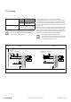
A stop is performed by switching off K3 and K4 via the
PLC. After the motor comes to a stop, as observed by the
zero-speed monitor, the spring-operated interlock can be
activated via the unlocking button and the safety door
can be opened. When the power supply is turned off, the
safety door cannot be opened if the locking mechanism is
engaged. We recommend using switches with mechanical
unlocking capabilities.
The PF-O-xDI-SIL switches on the 24V supply for the
following modules
1)
within the safety segment if:
– the emergency stop button is unlocked
– and the safety door is closed
– and the locking mechanism is engaged
– and the feedback circuit (NC contacts of K3 and K4) is
closed
– and the start push button has been pushed and released
again.
Contactors K3 and K4 are controlled by the PLC and can
switch on as soon as the PF-O-xDI-SIL has switched on
the 24V supply.