
User Documentation


5 Detailed descriptions of safe modules | Digital in- and output module UR20-4DI-4DO-PN-FSPS, UR20-4DI-4DO-PN-FSPS-V2
40 1484600000/07/11.2020u-remote IP20 modules for functional safety manual
4DI-4DO
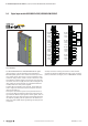
Module status LED
Green: Communication on system bus
3s green/1s red: Waiting for parameters
1s green/1s red: Waiting for acknowledgement by safety control
Red: Collective error diagnostic
1.1 Yellow: Input 0 active
1.3 Red: Error sensor supply or input 0 or input 1
1.4 Yellow: Input 1 active
2.1 Yellow: Input 2 active
2.3 Red: Error sensor supply or input 2 or input 3
2.4 Yellow: Input 3 active
3.1 Yellow: Output 0 active
3.2 Red: Error output 0
3.3 Yellow: Output 1 active
3.4 Red: Error output 1
4.1 Yellow: Output 2 active
4.2 Red: Error output 2
4.3 Yellow: Output 3 active
4.4 Red: Error output 3
LED indicators UR20-4DI-4DO-PN-FSPS, UR20-4DI-4DO-PN-FSPS-V2, error messages see Chapter7
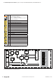
System
bus
U
SYS
U
IN
U
OUT
µC
µC
µC
24 V DC
GND
GND
DOx
4x
4x
2x
Config.
switch
DC
DC
1
2
3
4
DO 0 (PN)
GND
DO 1 (P)
GND
DI 0 (PN)
AUX-O 0
AUX-O 1
DI 1 (P)
DI 2 (PN)
AUX-O 2
AUX-O 3
DI 3 (P)
DO 2 (PN)
GND
DO 3 (P)
GND
Type 3
DI 0
•
•
DI 3
DO 0
•
•
DO 3
Block diagram UR20-4DI-4DO-PN-FSPS, UR20-4DI-4DO-PN-FSPS-V2