
User Documentation
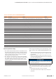

5 Detailed descriptions of safe modules | Digital in- and output module UR20-4DI-4DO-PN-FSOE, UR20-4DI-4DO-PN-FSOE-V2
24 1484600000/07/11.2020u-remote IP20 modules for functional safety manual
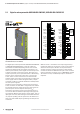
Digital in- and output module UR20-4DI-4DO-PN-FSOE (Best.-Nr. 1529780000),
UR20-4DI-4DO-PN-FSOE-V2 (Best.-Nr. 2464580000)
The digital input and output module UR20-4DI-4DO-PN-FSOE
or UR20-4DI-4DO-PN-FSOE-V2 is a safe I/O module for
the Fail-Safe-over-EtherCAT (FSoE) protocol. Each module
provides four digital inputs and outputs respectively, it can
detect up to four binary control signals and control up to four
actuators each with a maximum of 0.5A. Two inputs and
outputs respectively can be parameterised P- or N-switching.
Sensors can be connected to connectors 1 and 2 using a
2-wire, 3-wire or 4-wire connection. In the event that the
available supply current of 0.8A per plug will not sufce, the
sensor supply must be realised using the auxiliary outputs
of another module (e.g. potential distribution module) within
the same power segment.
Actuators can be connected to connectors 3 and 4 using a
2-wire connection. A status LED is assigned to each channel.
The module electronics supply the inputs as well as the out-
puts with power from the output current path (I
OUT
).
A test pulse check of the inputs can be parameterised as a
cross-circuit detection between input singal and supply volt-
age, between different input signals or other signals. Thus an
input gets active only when the signal of the dedicated auxil-
iary output is pending. The test pulses must be disabled, if a
safety relay with OSSD outputs generating own test pulses is
connected.
1
2
3
4
2
1
3
4
1
2
3
4
2
4
3
1
2
4
3
1
1
2
3
4
2
1
3
4
1
2
3
4
2
4
3
1
2
4
3
1
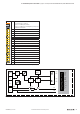
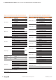
DO 0 (PN)
GND
DO 1 (P)
GND
DO 2 (PN)
GND
DO 3 (P)
GND
4DI·4DO
DI 0 (PN)
AUX-O 0
AUX-O 1
AUX-O 0
AUX-O 1
DI 1 (P)
DI 2 (PN)
AUX-O 2
AUX-O 3
DI 3 (P)
DO 0 (PN)
GND
DO 1 (P)
GND
DO 2 (PN)
GND
DO 3 (P)
GND
4DI·4DO
DI 0 (PN)
DI 1 (P)
DI 2 (PN)
AUX-O 2
AUX-O 3
DI 3 (P)
Safety relay
with OSSD
outputs
GND
24 V DC
Connection diagram UR20-4DI-4DO-PN-FSOE, UR20-4DI-4DO-PN-FSOE-V2 (Examples)
With the variant1 module the active output signal always
includes test pulses for the purpose of cross-circuit and error
detection. The test pulse duration can be parameterised.
A safety sensor that is being connected in a dual channel
mode must allocate the PN and the P-input of one connector
(safety architecture of category 4 acc. to DINENISO13849).
The external circuitry of a PN/P output pair is described in
Chapter3.
5.3 Digital in- and output module UR20-4DI-4DO-PN-FSOE, UR20-4DI-4DO-PN-FSOE-V2