
User Documentation


4 System description of safe power-feed modules | Sample design
16 1484600000/07/11.2020u-remote IP20 modules for functional safety manual
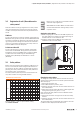
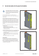
4.1 Sample design
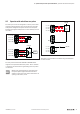
The following picture exemplies how to design a safety seg-
ment using a safe power-feed module. All output modules
arranged within the safety segment will be switched safely.
Input modules can be arranged within the safety segment,
only they do not fulll any safety function and are not inu-
enced by the PF-O-xDI-SIL module.
Safe I/O modules with outputs may not be posi-
tioned within a safety segment.
For detailed planning please also observe the
notes in the section „Conguration“.
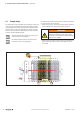
DI DI DO DIDODODO DO
PF-O
SIL
PF-OAO DO
FB
U
OUT
24 V Safe
U
OUT
24 V
U
IN
24 V
24 V
24 V
24 V
1
Example set-up of a safety segment (1) with PF-O-xDI-SIL
To switch the 24VSafe voltage back on, either an automatic
or a manual start can be selected.
– Automatic start: the safe output current path is switched
on immediately after resetting the safety circuit(s).
WARNING
Possible danger to life!
The option “Automatic start” might only be
used, after a risk analysis has shown that the
application is suitable.
– Manual start: the output current path is only switched on
again if the start button has been held down for 0.5 to
2seconds.