
User Documentation


3 System description of safe I/O modules | External circuitry of a PN/P output pair
12 1484600000/07/11.2020u-remote IP20 modules for functional safety manual
3.6 External circuitry of a PN/P output pair
All information in this section refer to the ZVEI position paper
CB24I (Edition 2.0).
The outputs of the module can be circuited as follows.
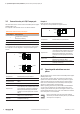
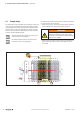
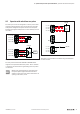
Options for the external circuitry of the outputs
Circuit diagram Parameterisation
1
2 x single-channel, P-switching
or
dual-channel, P-switching
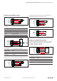
2 2 x single-channel, rst channel N-switching
3 dual-channel, rst channel N-switching
Examples 1 and 2
2 x single-channel, P-switching or dual-channel, P-switching
The outputs in circuit diagram1 correspond to the typeC
source.
1
2
3
4
1
2
3
4
1
2
3
4
DO (PN)
DO (P)
DO (PN)
24 V DC
DO (P)
DO (PN)
DO (P)
1
2
3
External circuitry of the outputs
Test pulse class Parameterisable per test pulse duration
Test pulse duration Depending on the parameterisation 0.5 ... 10ms
Test pulse intervall 200ms
Rated current 0.5A (as per EN61131-2)
Capacitive load
Depending on the parameterisation and the load
current. With test pulses enabled the output current
must be reduced to <10V within one millisecond.
With test pulses disabled (only possible with V2
modules) the connected capacity must not exceed
250µF.
Inductive load
As per EN61131-2 for 0.5Aoutputs, maximum
leakage current in state OFF: 100µA
Lamp load
When using a lamp load the test pulses must be
enabled (V2 modules only).
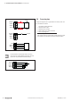
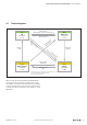
Example 3
Dual-channel, rst channel N-switching
The outputs correspond with the typeD source.
1
2
3
4
1
2
3
4
1
2
3
4
DO (PN)
DO (P)
DO (PN)
24 V DC
DO (P)
DO (PN)
DO (P)
1
2
3
External dual-channel circuitry of the outputs
Test pulse class Parameterisable per test pulse duration
Test pulse duration Depending on the parameterisation 0.5 ... 10ms
Test pulse intervall 200ms
Rated current 0.5A (as per EN61131-2)
Capacitive load
Depending on the parameterisation and the load
current. With test pulses enabled the output current
must be reduced to <10V within one millisecond.
With test pulses disabled (only possible with V2
modules) the connected capacity must not exceed
250µF.
Inductive load
As per EN61131-2 for 0.5Aoutputs, maximum
leakage current in state OFF: 100µA
Lamp load
When using a lamp load the test pulses must be
enabled (V2 modules only).
3.7 Operating with and without own test
pulses
All information in this section refer to the ZVEI position paper
CB24I (Edition 2.0).
The parameter settings allow to enable test pulses for the
inputs of the safe I/O modules. These test pulses are gener-
ated and analysed by the module. Thus the highest safety
levels can be achieved (see technical data). The test pulse
duration is determined by the input delay.
When operating without test pulses AUX-OX and AUX-OY
can be used as outputs for the supply voltage. The active
output signal includes test pulses, the length of which is pa-
rameterisable between 0.5ms and 10ms. With V2 modules
these test pulses can be disabled.
Please regard the notes for parameter settings
whenever you disable the test pulses (see module
descriptions in chapter5).