Remote-I/O-System u-remote Web server manual Letʼs connect.
Content Manufacturer Weidmüller Interface GmbH & Co. KG Klingenbergstraße 16 32758 Detmold, Germany T +49 5231 14-0 F +49 5231 14-292083 www.weidmueller.com 1 1.1 1.2 1.3 Introduction About this documentation Complete documentation General safety notice 3 3 3 3 2 2.1 2.2 2.3 Connecting the web server and getting startet Requirements Installing the web server via USB Starting the web server 4 4 4 5 3 3.1 3.2 3.3 3.4 3.5 3.6 3.7 3.
1 Introduction With the web server, the u-remote station is displayed on a connected PC. This allows you to carry out the following tasks e.g.
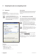
2 Connecting the web server and getting startet 2.1 Requirements Screen resolution Operating system The u-remote web server is designed for operation with the Windows XP®, Windows 7® and Windows Vista® operating systems. For operation with Windows XP: if you installed the Siemens Primary Setup Tool, the DLC (data link control) protocol was also installed. To access the web server, you must deactivate the DLC protocol on the USB interface (LAN connection with WI-UR20-FBC).
Connecting the web server and getting startet | Starting the web server 2.3 Starting the web server The u-remote station must be completely assembled and supplied with voltage. ▶▶ Connect the PC to the coupler using a USB cable. The USB socket at the coupler can be found behind the service flap on the front side. ▶▶ Open one of the browsers listed in section 2.1 ▶▶ In the address line, enter the IP address of the coupler (default: 192.168.1.202, UR20-FBC-EIP: 192.168.5.202). The web server is started.
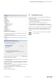
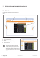
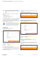
3 Getting to know and arranging the web server 3.1 Station view The station view is displayed on every start up of the web server. 2 3 4 1 5 Station view with operating elements 1 2 3 4 5 Switch over to the component list (by mouseover) Access to the web server functions Menue bar Detail view of module/channel (by mouseover) Switch over to the component view (by mouse click) Scaling the view up or down The web server only registers modules that can communicate on the system bus.
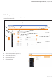
Getting to know and arranging the web server | Component view 3.2 Component view The component view is opened after clicking on a component or the component list.
Getting to know and arranging the web server | Navigation 3.3 Navigation When using a smaller view you can scale up single components by a mouseover. There are several options how to display the station or certain components (coupler or modules): Station view This view shows all components and you can display details via mouseover. You can open the station view with a click on “Overview”. Component view Here you see a single component (coupler or module) with its information and parameter settings.
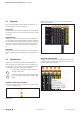
Getting to know and arranging the web server | Setting the language Showing/hiding content You can open all entries marked with a plus symbol by a single mouse click so that the content will be displayed. 3.5 Setting the language Changing the language When the program is started, the web server attempts to start with the language set in your web browser. If this language is not supported by the web server, the program starts with the “English” setting.
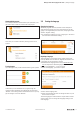
Getting to know and arranging the web server | Setting up login data and password protection 3.6 Setting up login data and password protection Password protection restricts the access to the following functions: –– Change parameters –– Operate the station in force mode –– Load firmware updates Users without a user ID will only have read-only rights. Write access is blocked for them, which means that they cannot use the listed functions.
Getting to know and arranging the web server | Setting up the Ethernet socket 3.7 Setting up the Ethernet socket 3.8 If you want to use the web server via Ethernet you have to set up the ethernet connection fist. ▶▶ Connect the PC with the coupler (or a switch within the network) using a LAN cable. ▶▶ Click on the coupler in the station view and then on “Parameter“. ▶▶ Define the IP address, subnet mask and gateway to be used. ▶▶ Make sure, that the parameter “Webserver over Ethernet” is enabled.
Getting to know and arranging the web server | HTTPS Call up the web server via HTTPS The computer must be connected with the u-remote station. The u-remote station must be assembled in full and powered up. ▶▶ Open one of the browsers listed in section 2.1. ▶▶ In the address line, enter “https://” and the IP address of the coupler (default: 192.168.1.202, UR20-FBC-EIP: 192.168.5.202).
Getting to know and arranging the web server | HTTPS Restart the web server The web server is restarted. After the restart, the user-defined certificate is activated. Exchange TLS/SSL certificate User-defined certificate successfully activated ▶▶ Delete any old keys and certificates by clicking on “Delete”. ▶▶ Load the key and the certificates onto the coupler by clicking on “Select file” and then select the relevant file from your computer. Keys and certificates are automatically checked.
4 Coupler settings ▶▶ Open the coupler component view. Displaying and changing the coupler settings Coupler component view Here you can: –– Access and change the coupler parameters –– Query diagnoses –– Query general information about the coupler –– Type in I&M data (Identification & Maintenance) –– Change the login data and set up password protection (see section 3.6).
Coupler settings | Resetting the coupler to factory settings 4.4 Calling up the data sheet ▶▶ Click on “Ordering data” to open the data sheet of the coupler. A connection to the Weidmüller website is established in a new window and the data sheet will be shown in a PDF file. Restarting web server and coupler The coupler as well as the web server are restartet. 4.3 Resetting the coupler to factory settings This function allows you to set up the coupler in its original state as at delivery.
5 Module settings ▶▶ Open the module component view. Displaying and editing module parameters Module component view Here you can: –– Query general information about the module –– Access and change the module parameters –– Query information about certain channels –– Access the data sheet of the module (link “Ordering data“) The module settings are only accessible when force mode is not active. ▶▶ Enter the desired modifications. Each change is marked with a green symbol until it will be applied.
Module settings | Displaying register settings 5.2 Displaying register settings For modules with registers (e.g. counter modules and PWM modules), the register settings can be displayed in a tool tip. ▶▶ Open the module component view. ▶▶ Move the cursor over the value of the register you want to see. Displaying the register settings The registers displayed in bold are set, all of the others are not set. 5.3 Calling up the data sheet ▶▶ Click on “Ordering data“ to open the data sheet of the module.
6 Configuration and station data 6.1 Save/load configuration When using PROFINET or PROFIBUS you can continue working. ▶▶ With all other fieldbus protocols you have to restart the coupler. You can save the current configuration of the u-remote station or load an existing configuration into the coupler. This makes arranging several stations of identical setup very easy.
Configuration and station data | Displaying process data –– Never use mutated vowel, commas or semicolons for tag names. The structure of modules and channels may not be changed in this file, otherwise it will no longer be compatible with the station. –– In the event that you use special characters make sure to safe the CSV-file UTF-8-encoded. Editing the CSV-file using Microsoft® Office Excel® The file will be loaded into the coupler and the current channel names will be displayed in the web server.
Configuration and station data | Displaying diagnostic data (alarms) 6.4 Displaying diagnostic data (alarms) ▶▶ Click on “Station data“ and then on “Alarms“. Opening diagnostic data The overview displays all current alarms. Components without diagnostic message are not displayed. Display of diagnostic data 20 u-remote web server manual 2112220000/05/01.
7 Web server in force mode 7.1 Activating the force mode WARNING! Manipulation of the control unit! In force mode, the system may be manipulated to such an extent that can result in lifethreatening personal injury and damage to materials. Only use force if you are very familiar with the connected system and know at all times the consequences that your actions will have! If the force mode is activated during an established field bus connection a diagnose alarm is generated.
Web server in force mode | Forcing via the station view 7.2 Forcing via the station view ▶▶ Click on the channel to be forced. Dependent on the module type there are different options: ▶▶ To switch an output, click on the switch and then on “Force“. Forcing registers ▶▶ Set or remove the arrow for each register to be forced and click on “Apply changes“. ▶▶ Click on “Force“. The changes are transferred to the coupler.
Web server in force mode | Ending/deactivating force mode Detail view of the station in force mode All active modules are displayed in the overview. The switchable channels are provided with a changeover switch. ▶▶ To see all channel details, click on “Show all“. ▶▶ To see only the first value of each channel, click on “Hide all“. Filtering the module view If you only want to see the modules that you would like to force, use the filter function. ▶▶ Click on the plus symbol besides “Filter“.
8 Updating firmware ▶▶ Download the latest firmware file for each component you want to update from the Weidmüller website to your local PC. Firmware files for fieldbus couplers have the extension “.bsc”. For PROFINET couplers, for instance, the file might be named FBC-PN-IRT-00XX.bsc. The compatibility is checked during uploading the coupler firmware. Thus it is not possible to load a incompatible coupler firmware. Firmware files for modules have the extension “. bsm”.
Updating firmware | Ending/deactivating force mode The firmware is updated. Once the data has been transferred, you are asked to restart the coupler ▶▶ Click on “Reset”. ▶▶ Wait until the coupler has been restartet and the station view is displayed in the web server. In case the web server does not restart, please act as follows: ▶▶ Clear the temporary browser data (cache). Deleting the browser protocol is not sufficient. ▶▶ Start the web server again. 2112220000/05/01.
9 Help and FAQ 9.1 The web server cannot be loaded –– Are coupler and PC connected via an USB cable in a propiate way? –– Is the correct IP address set for the USB port (see section 9.2) –– Clear the temporary browser data (empty cache, deleting the browser protocol is not sufficient) and reload the web server. –– If you call up the web server via HTTP, try calling up the web server via HTTPS.
Help and FAQ | Documentation 9.4 Documentation ▶▶ Click on “Help” underneath the menue bar. Help dialogue box The program version of the web server is displayed in the help dialogue box. ▶▶ To open the manuals for the u-remote station and the webserver, click on the link. A connection to the Weidmüller website is established in a new window. 2112220000/05/01.
Weidmüller – Your Partner in Industrial Connectivity As experienced experts we support our customers and partners around the world with products, solutions and services in the industrial environment of power, signal and data. We are at home in their industries and markets and know the technological challenges of tomorrow. We are therefore continuously developing innovative, sustainable and useful solutions for their individual needs. Together we set standards in Industrial Connectivity.