
User Documentation


8 LED displays and troubleshooting | Safe I/O modules
89u-remote IP20 modules for functional safety manual 1484600000/07/11.2020
In the event of a malfunction occurring on a u-remote sta-
tion, carry out the following recommended measures. If the
malfunction cannot be xed, please send the affected prod-
uct to Weidmüller.
You can nd all Weidmüller addresses and your local con-
tact on the Internet at www.weidmueller.com/countries.
Weidmüller does not assume any liability if the base or
electronic module has been tampered with!
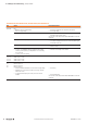
8.1 Safe I/O modules
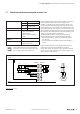
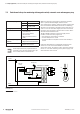
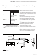
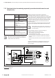
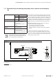
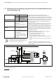
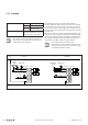
UR20-4DI-4DO-PN-FSOE, UR20-4DI-4DO-PN-FSOE-V2, UR20-4DI-4DO-PN-FSPS, UR20-4DI-4DO-PN-FSPS-V2
LED Status Recommended action
Status LED Red:
– Module has not been snapped properly
– Error in the supply voltage
– Check that the module has been snapped into place properly
– Check supply voltage
– Internal error detected – Module might have switched off caused by overtemperature; check the
temperature inside the switch cabinet
If the error has not been xed, send the module to Weidmüller for a technical
examination.
– Safety address is not set properly – Check the safety address (e.g. via the web server)
– If no address is displayed in the web server set the safety address again
as described in section 3.5
– Communication failure – Check wiring
– Restart the coupler
Flashes alternating red and green
– 3s green / 1s red: Module is waiting for parameters from the safety
control (e.g. after the power up) or safety address is not set according
to the project plan
– 1s green / 1s red: Error pending
– Intervention via the safety control is needed
– Set the correct safety address
– Check the parameter check sum in the project planning
– Status must be acknowledged via the safety control
1.1 / 1.4
2.1 / 2.4
Yellow: Input 0 / 1 active
Yellow: Input 2 / 3 active
1.3
2.3
Red: Error input 0 / 1
Red: Error input 2 / 3
– At least one AUX-O is overloaded or short circuit with the supply voltage
– Readback error on the test pulses of at least one input (e.g. caused by
external short circuit)
– The parameterised discrepancy time of this pair of inputs has been
exceeded
– Check wiring
– Check parameterisation
If the error has not been xed, send the module to Weidmüller for a technical
examination.
3.1 / 3.3
4.1 / 4.3
Yellow: Output 0 / 1 active
Yellow: Output 2 / 3 active
3.2 / 3.4
4.2 / 4.4
Red: Error output 0 / 1
Red: Error output 2 / 3
– Output is overloaded
– Short circuit with the supply voltage or ground or cross-fault with
another channel
– Minimum load has been underrun (e.g. after wire break)
– Readback error
– Check wiring
– Check whether the load circuit is interrupted
If the error has not been xed, send the module to Weidmüller for a technical
examination.
8 LED displays and troubleshooting