
User Documentation


8 LED displays and troubleshooting | Safe power-feed modules
92 1484600000/07/11.2020u-remote IP20 modules for functional safety manual
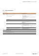
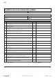
UR20-PF-O-2DI-SIL, UR20-PF-O-2DI-DELAY-SIL
LED Status Recommended action
Status LED Red:
– Module has not been snapped properly
– Error in the supply voltage
– Channel error
– Check that the module has been snapped into place properly
– Check the supply voltage:
1. check +24V input current path
2. check voltage on plug 4.3; in case of cascading 0V might be properly,
therefore this is not an error
– Check channel error
– Overload at the 24V Safe output level – Remove cross connection at 24V Safe
– External feed-in recognised from field side – Measure voltage at 24V Safe (4.3) vs. GND (4.4).
If a voltage is present, check the wiring!
Attention: safety hazard! Shut down the system and prevent it from
switching on again!
– Internal error detected – Module might have switched off caused by overtemperature; check the
temperature inside the switch cabinet
– Perform a cold start within 24 hours.
If the error has not been xed, send the module to Weidmüller for a technical
examination
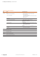
– Interruption in one of the two safety loops of a safety circuit for at least
3 seconds.
– Check safety circuit for interruptions if an interruption of the safety
channel is not part of the application
– Cross connection between the safety loops for at least 3 seconds. – Check safety circuit for cross connections
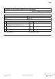
1.1 Off: Safety circuit 1 interrupted
Yellow: Safety circuit 1 OK
Check safety circuit 1
2.1 Off: Safety circuit 2 interrupted
Yellow: Safety circuit 2 OK
Check safety circuit 2
4.1
(DELAY only)
Off: SS1 not active
Yellow: SS1 active, 24VDC at output
4.2 Off: 24V Safe not active
Yellow: 24V Safe active, 24VDC at output
4.3 Green: Feed-in voltage in valid range