
User Documentation


3 System description of safe I/O modules | Registration of safe I/O modules on the safety control
11u-remote IP20 modules for functional safety manual 1484600000/07/11.2020
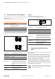
3.4 Registration of safe I/O modules on the
safety control
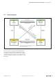
Safe I/O modules need to get registered on a safety control
using an engineering tool. Via the web server the safe I/O
modules can only be observed but not be parameterised or
forced.
PROFIsafe
For the commissioning of safe I/O modules running with the
PROFIsafe safety protocol you will need the Weidmüller CPD
tool which is available to download on the website. Accord-
ing to the parameter settings this software tool calculates a
check sum, wich will be transferred to the safety control in
Siemens STEP7 and on the TIA portal.
Fail-Safe-over-EtherCAT
For the commissioning of safe I/O modules running with
the Fail safe over EtherCAT safety protocol you will need
TwinCAT as well as a TwinSAFE safety control. The FSOE
modules have been tested using the TwinSAFE-Logic
EL6900 system (Beckhoff) and TwinCAT 2.11.2247
(Beckhoff).
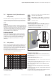
3.5 Safety address
Before commissioning the safety address (F-address) has to
be set on each safe I/O module using the DIP switches on
the electronic unit. This address is indicated by the project
planning. The safety control transfers the safety address to
the module on each commissioning.
The safety address (decimal) has to be converted into a bi-
nary value and then set using the DIP switches .
Decimal/binary conversion table
decimal 2048 1024 512 256 128 64 32 16 8 4 2 1
binary
0 0 0 0 0 0 0 0 0 0 0 1
0 0 0 0 0 0 0 0 0 0 1 0
0 0 0 0 0 0 0 0 0 1 0 0
0 0 0 0 0 0 0 0 1 0 0 0
0 0 0 0 0 0 0 1 0 0 0 0
0 0 0 0 0 0 1 0 0 0 0 0
0 0 0 0 0 1 0 0 0 0 0 0
0 0 0 0 1 0 0 0 0 0 0 0
0 0 0 1 0 0 0 0 0 0 0 0
0 0 1 0 0 0 0 0 0 0 0 0
0 1 0 0 0 0 0 0 0 0 0 0
1 0 0 0 0 0 0 0 0 0 0 0
1234 0 1 0 0 1 1 0 1 0 0 1 0
Example: Address „1234“ is represented by setting
0000010011010010.
Please use e.g. a ball pen to set the DIP switches
and avoid sharp-edged tools.
With PROFIsafe modules: Make sure that switch-
es without identication marking always remain
in position “Zero”.
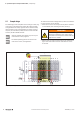
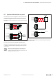
Setting the safety address
▶ Before snapping the module onto the DIN rail please set
the safety address according to the project planning via
the DIP switches on the electronic unit.
▶ Snap the module onto the DIN rail and continue the
installation of the u-remote station.
1 0
3
2
1
0
7
6
5
4
11
10
9
8
0000010011010010
1 0
3
2
1
0
7
6
5
4
11
10
9
8
DIP switches for setting the safety address (example setting: 1234)
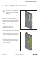
Changing the safety address
To change the safety address after the module has been as-
signed to the control please act as follows (with V2 modules
start with step5):
1. Pull out the electronic unit.
2. Set all DIP switches to position „Zero“.
3. Slide the electronic unit back into the module and turn on
the module/station.
4. Please wait until the status LED of the module lights alter-
nating red and green (3 s green, 1 s red).
Only now the old safety address has been deleted and the
new one can be set.
5. Pull out the electronic unit again and set the new safety
address.
6. Slide the electronic unit back into the module and turn on
the module/station.
The status LED of the module lights green and the new safe-
ty address will be displayed on the web server.