
User Documentation
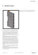


4 Modulbeschreibung | Anschlüsse
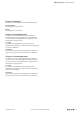
13Handbuch Kommunikationsmodul UR20-4COM-IO-LINK2547620000/03/08.2019
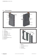
4.2 Anschlüsse
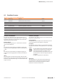
IO-LINK
Device
IO-LINK
Device
IO-LINK
Device
IO-LINK
Device
1
2
3
4
2
1
3
4
1
2
3
4
2
4
3
1
2
4
3
1
4 IO LINK
C/Q 1
L+ 1
DI 1
C/Q 2
L+ 2
DI 2
C/Q 3
L+ 3
DI 3
C/Q 4
L+ 4
L– 1
L– 2
L– 3
L– 4
DI 4
Anschlussbild UR20-4COM-IO-LINK
Ein Steckverbinder entspricht einem IO-Link-Port vom TypA.
Steckverbinder Anschluss Signal Funktion
1 C/Q IO-Link-Kommunikation
2 L- GNDIN
3 L+ 24VDCIN
4 DI Digitaler Eingang (Typ 1)
Eine Beschreibung, wie IO-Link-Devices für beide Portklassen
und Standardfeldgeräte an das Modul angeschlossen wer-
den, nden Sie in Kapitel 5.
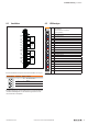
4.3 LED-Anzeigen
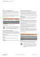
4 IO LINK
Status-LED Modul
Grün: Kommunikation auf Systembus
Rot: Störungsmeldung
1.1 Gelb: Status COM 1
1.2 Rot: Fehler IO-Link-Port 1
1.4 Gelb: Status DI 1
2.1 Gelb: Status COM 2
2.2 Rot: Fehler IO-Link-Port 2
2.4 Gelb: Status DI 2
3.1 Gelb: Status COM 3
3.2 Rot: Fehler IO-Link-Port 3
3.4 Gelb: Status DI 3
4.1 Gelb: Status COM 4
4.2 Rot: Fehler IO-Link-Port 4
4.4 Gelb: Status DI 4
LED-Anzeigen UR20-4COM-IO-LINK