
User Documentation
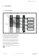

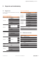
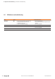
Table Of Contents
- Content
- 1 About this documentation
- 2 Safety
- 3 IO-Link overview
- 4 Module description
- 5 Assembly and installation
- 6 Commissioning
- 6.1 Requirements
- 6.2 Device description files
- 6.3 Procedure for commissioning
- 6.4 Commissioning with the SIMATIC Manager (PROFINET)
- 6.5 Commissioning with the TIA portal(PROFINET)
- 6.6 Commissioning with TwinCAT (EtherCAT)
- 6.7 Commissioning with Studio 5000(Ethernet/IP)
- 6.8 Commissioning with Automation Studio (POWERLINK)
- 6.9 Reading and writing data objects on IO-Link devices
- 6.10 “IO_LINK_CALL” function block
- 6.11 I&M functions
- 7 Planning IO-Link device configurations
- 8 Process data
- 9 Diagnostics and troubleshooting
- 10 Disassembly and disposal
9 Diagnosticsandtroubleshooting | LED indicators and troubleshooting
56 2547720000/03/09.2019Manual Communication module UR20-4COM-IO-LINK
9.3 LED indicators and troubleshooting
LED Status Recommended action
Status LED Red: – Error in the supply voltage at input current path
– Communication error on the system bus
– Configuration error IO-Link
– There is a new diagnostic message
– Check the supply voltage
– Check that the module has been snapped into place
properly
– Check the configuration
Channel LED 1.1...4.1 Yellow: – Status COM 1...COM4
–
1.2...4.2 Red: – Fehler IO-Link port1...IO-Link port4 – Check the wiring
– Check the configuration
1.4...4.4 Yellow: – Status DI1...DI4
–