
User Documentation
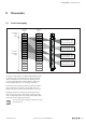
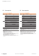
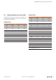
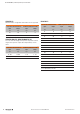

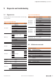
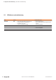
Table Of Contents
- Content
- 1 About this documentation
- 2 Safety
- 3 IO-Link overview
- 4 Module description
- 5 Assembly and installation
- 6 Commissioning
- 6.1 Requirements
- 6.2 Device description files
- 6.3 Procedure for commissioning
- 6.4 Commissioning with the SIMATIC Manager (PROFINET)
- 6.5 Commissioning with the TIA portal(PROFINET)
- 6.6 Commissioning with TwinCAT (EtherCAT)
- 6.7 Commissioning with Studio 5000(Ethernet/IP)
- 6.8 Commissioning with Automation Studio (POWERLINK)
- 6.9 Reading and writing data objects on IO-Link devices
- 6.10 “IO_LINK_CALL” function block
- 6.11 I&M functions
- 7 Planning IO-Link device configurations
- 8 Process data
- 9 Diagnostics and troubleshooting
- 10 Disassembly and disposal
9 Diagnosticsandtroubleshooting | Diagnostic data
55Manual Communication module UR20-4COM-IO-LINK2547720000/03/09.2019
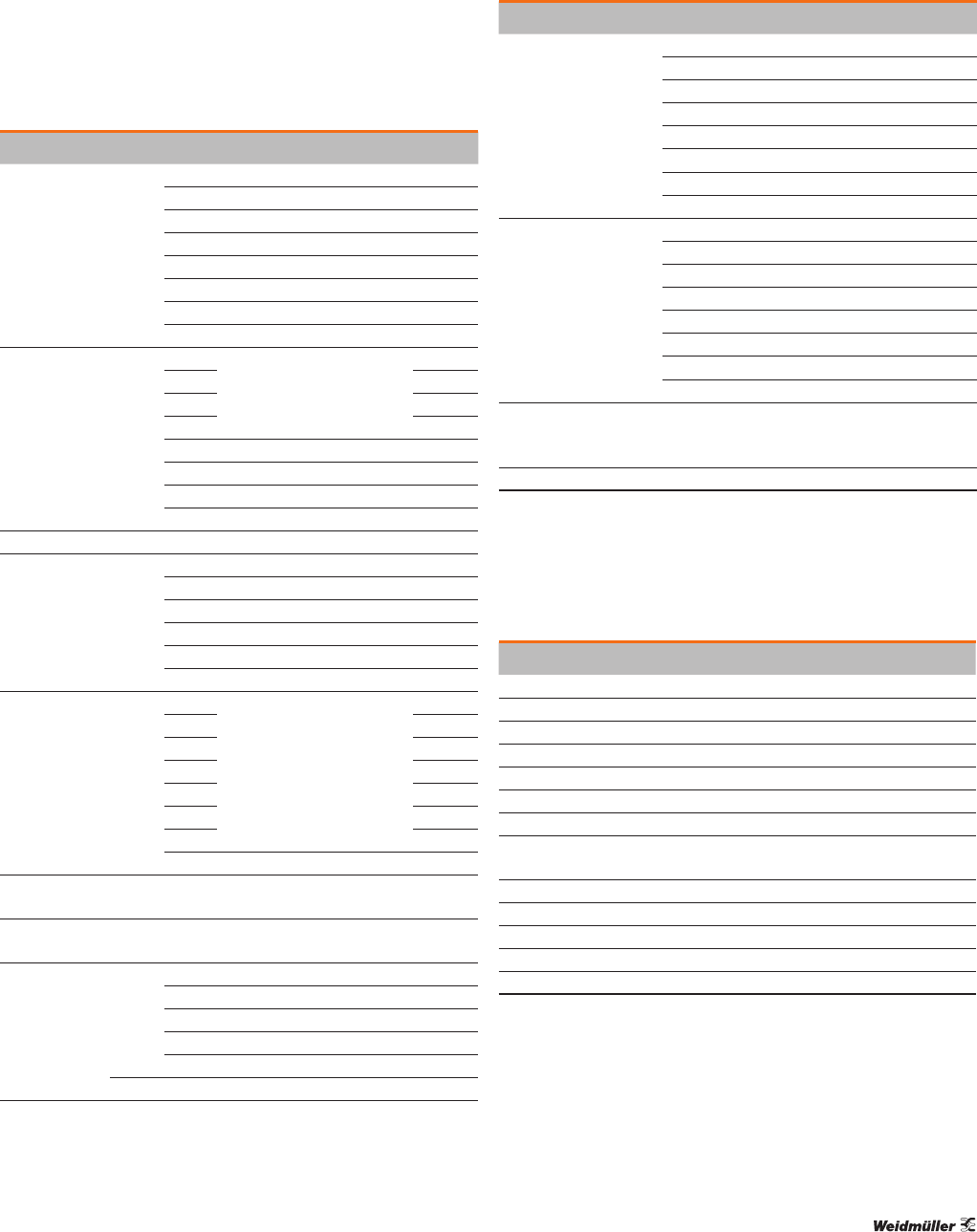
9.1 Diagnostic data
Channel diagnoses can be activated with the “Channel diag-
nosis” parameter.
Diagnostic data UR20-4COM-IO-LINK
Name Byte Bit Description Default
Error indicator 0
0 Module error 0
1 Internal Error 0
2 External error 0
3 Channel error 0
4 Error 0
5 Power supply fault 0
6 Reserved 0
7 Parameter error 0
Module type 1
0
Module Type 0x05
1
2
3
4 Reserved 1
5 Reserved 0
6 Reserved 0
7 Reserved 0
Error byte 2 2 0 ... 7 Reserved 0
Error byte 3 3
0 ... 2 Reserved 0
3 Diagnostic Alarm Lost 0
4 Communication fault 0
5 Reserved 0
6 Reserved 0
7 IO-Link Event in Queue 0
Channel type 4
0
Channel type
1
1 1
2 0
3 1
4 1
5 1
6 1
7 Reserved 0
Diagnostic bits
per channel
5
Number of diagnostic bit per
channel
16
Number of
channels
6
Number of similar channels per
module
4
Channel error
7
0 Error at channel 0 0
1 Error at channel 1 0
2 Error at channel 2 0
3 Error at channel 3 0
4 ... 7 Reserved 0
8 ... 10 8 ... 31 Reserved 0
Diagnostic data UR20-4COM-IO-LINK
Name Byte Bit Description Default
Error channel 0
Error channel 1
Error channel 2
Error channel 3
11
13
15
17
0 Short Circuit 0
1 Undervoltage 0
2 Overvoltage 0
3 Overload 0
4 Overtemperature 0
5 Line Break 0
6 Upper Limit Value
7 Lower Limit Value 0
Error channel 0
Error channel 1
Error channel 2
Error channel 3
12
14
16
18
0 Error 0
1 Parameter fault 0
2 Powersupply fault 0
3 Fuse blown 0
4 Communication fault 0
5 Error 1 0
6 Unknown Error
7 Unknown Error 2 0
Error channel 4
...
Error channel 15
19
...
42
0 ... 7 Reserved 0
Time stamp 43-46 time stamp [µs] (32bit)
9.2 IO-Link master event codes
Event Code Description
0xC101 Overcurrent at transmitter
0xC102 Overtemperature at transmitter
0xC103 Undervoltage at VDD
0xC104 Undervoltage at VDDH
0xC105 Undervoltage at L+
0xC106 Overcurrent at L+ shunt
0xC201 Error at Data Storage EEPROM access
0xFF21 A new connection has been established between the Master and
the Device
0xFF22 The Device hasn‘t answered for three consequent Master request
0xFF23 DS header settings doesn‘t match with the read IDs
0xFF24 The DS buffer overows
0xFF25 A DS parameter can‘t be accessed
0xFF91 Request DS upload
9 Diagnostics and troubleshooting