
User Documentation

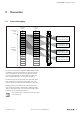
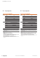
Table Of Contents
- Content
- 1 About this documentation
- 2 Safety
- 3 IO-Link overview
- 4 Module description
- 5 Assembly and installation
- 6 Commissioning
- 6.1 Requirements
- 6.2 Device description files
- 6.3 Procedure for commissioning
- 6.4 Commissioning with the SIMATIC Manager (PROFINET)
- 6.5 Commissioning with the TIA portal(PROFINET)
- 6.6 Commissioning with TwinCAT (EtherCAT)
- 6.7 Commissioning with Studio 5000(Ethernet/IP)
- 6.8 Commissioning with Automation Studio (POWERLINK)
- 6.9 Reading and writing data objects on IO-Link devices
- 6.10 “IO_LINK_CALL” function block
- 6.11 I&M functions
- 7 Planning IO-Link device configurations
- 8 Process data
- 9 Diagnostics and troubleshooting
- 10 Disassembly and disposal
8 Processdata | Process input data
50 2547720000/03/09.2019Manual Communication module UR20-4COM-IO-LINK
8.2 Process input data
Process data inputs UR20-4COM-IO-LINK
Byte Bit Description
IB0
IX0.0 DI 1
IX0.1 DI 2
IX0.2 DI 3
IX0.3 DI 4
IX0.4 C/Q 1
IX0.5 C/Q 2
IX0.6 C/Q 3
IX0.7 C/Q 4
IB1
IX1.0 Process data IN valid IO-Link-Port 1
IX1.1 Process data IN valid IO-Link-Port 2
IX1.2 Process data IN valid IO-Link-Port 3
IX1.3 Process data IN valid IO-Link-Port 4
IX1.4 Error IO-Link-Port 1
IX1.5 Error IO-Link-Port 2
IX1.6 Error IO-Link-Port 3
IX1.7 Error IO-Link-Port 4
IB2 ... Process data of the IO-Link device
1)
1) The process data length of the IO-Link devices is adjustable. The mapping
of the IO-Link devices depends on the length of their process data and the
parameter settings.
– DIX:
Status DI on channel X.
– C/QX: Status C/Q on channel X.
– Process data IN valid channel X: Process input data
of the IO-Link devices at IO-Link portX valid.
– Error channel X: Error on channel X.
– Process input data of the IO-Link devices: seesec-
tion 8.1.
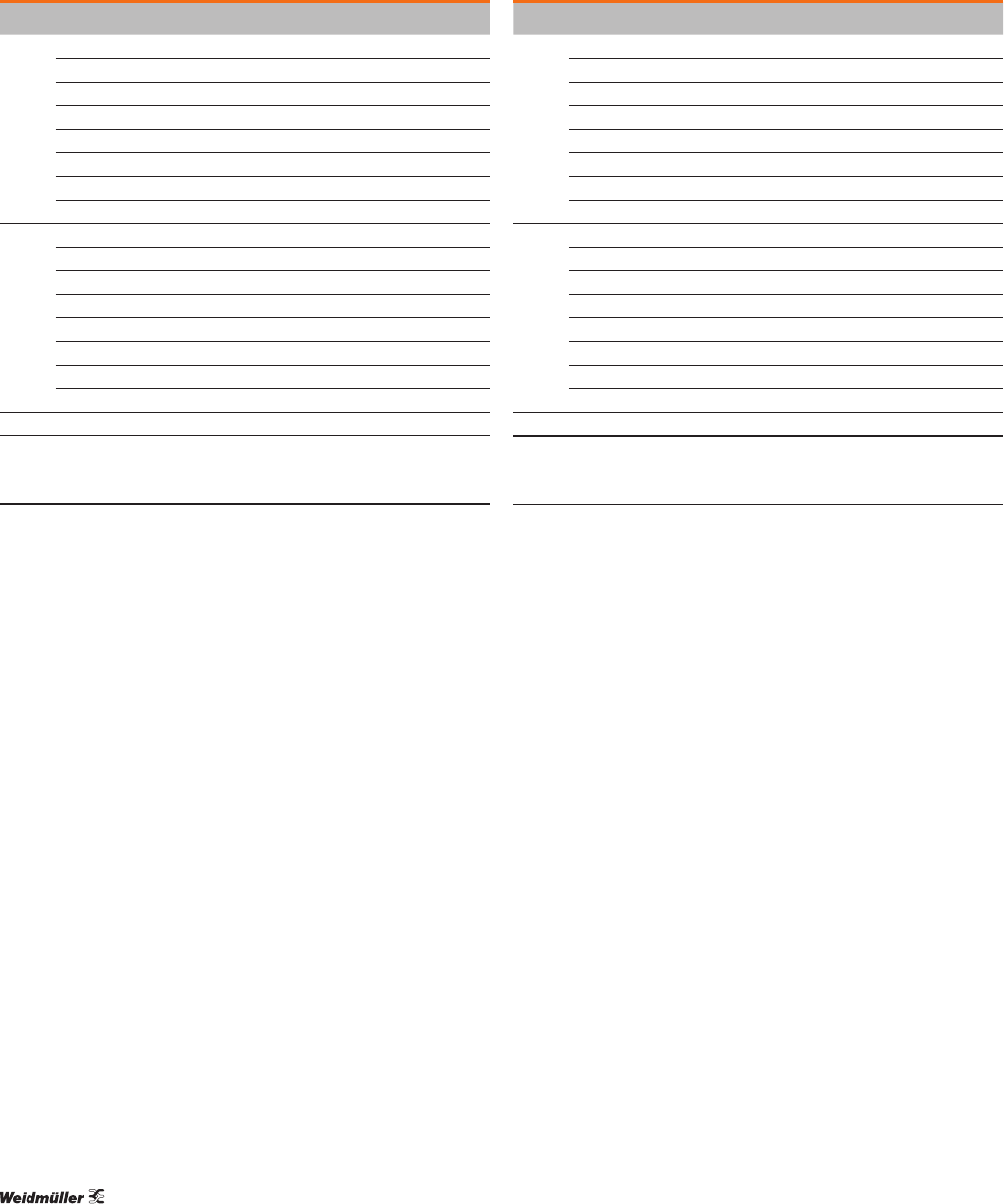
8.3 Process output data
Process data outputs UR20-4COM-IO-LINK
Byte Bit Description
OB0
OX0.0 DO 1
OX0.1 DO 2
OX0.2 DO 3
OX0.3 DO 4
OX0.4 reserved
OX0.5 reserved
OX0.6 reserved
OX0.7 reserved
OB1
OX1.0 Process data OUT valid IO-Link-Port 1
OX1.1 Process data OUT valid IO-Link-Port 2
OX1.2 Process data OUT valid IO-Link-Port 3
OX1.3 Process data OUT valid IO-Link-Port 4
OX1.4 reserved
OX1.5 reserved
OX1.6 reserved
OX1.7 reserved
OB2 ... Process data of the IO-Link device
1)
1) The process data length of the IO-Link devices is adjustable. The mapping
of the IO-Link devices depends on the length of their process data and the
parameter settings.
– DOX:
Control C/Q on channel X in DI operation mode.
– Process data OUT valid channelX: Process output
data of the IO-Link devices on channel X valid.
– Process output data of the IO-Link devices: see sec-
tion 8.1