
User Documentation
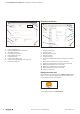
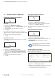
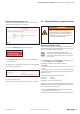
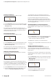

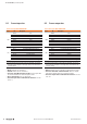
Table Of Contents
- Content
- 1 About this documentation
- 2 Safety
- 3 IO-Link overview
- 4 Module description
- 5 Assembly and installation
- 6 Commissioning
- 6.1 Requirements
- 6.2 Device description files
- 6.3 Procedure for commissioning
- 6.4 Commissioning with the SIMATIC Manager (PROFINET)
- 6.5 Commissioning with the TIA portal(PROFINET)
- 6.6 Commissioning with TwinCAT (EtherCAT)
- 6.7 Commissioning with Studio 5000(Ethernet/IP)
- 6.8 Commissioning with Automation Studio (POWERLINK)
- 6.9 Reading and writing data objects on IO-Link devices
- 6.10 “IO_LINK_CALL” function block
- 6.11 I&M functions
- 7 Planning IO-Link device configurations
- 8 Process data
- 9 Diagnostics and troubleshooting
- 10 Disassembly and disposal
7 PlanningIO-Linkdevicecongurations | Editing IO-Link device congurations online
45Manual Communication module UR20-4COM-IO-LINK2547720000/03/09.2019
Finding and rectifying parameter errors
Faulty parameterised IO-Link devices are indicated by a red
frame around the IO-Link port concerned.
Faulty parameterised IO-Link device
▶ Open the detailed view of the IO-Link device.
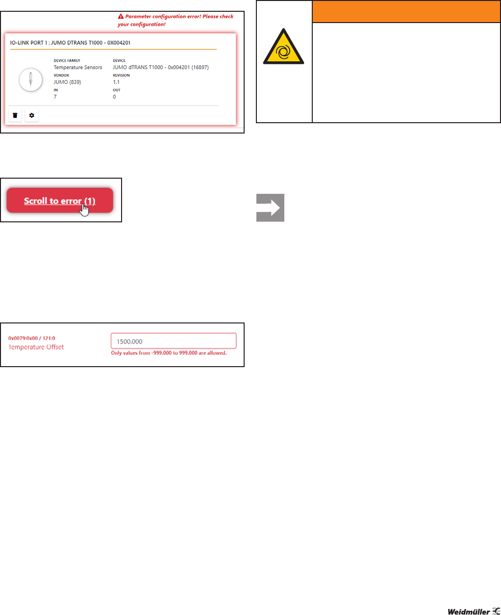
Jumping to the faulty parameter entry
▶ Click Scroll to error in order to jump to the next faulty
parameter entry.
The faulty entry is indicated by a red frame. A note regarding
error diagnosis is displayed.
Faulty parameter entry
▶ Correct the faulty entry.
▶ Repeat the procedure until all errors have been rectified.
7.5 EditingIO-Linkdevicecongurationsonline
WARNING!
Manipulation of the control unit!
During commissioning, the system may be
manipulated to such an extent that this can
result in risks to life and material damage.
▶ Make sure that system components can-
not start up unintentionally!
Connectingtotheeldbuscoupler
The u-remote station must be completely assembled and
supplied with voltage. The computer must be connected to
the u-remote station via USB or Ethernet.
If you access a eldbus coupler via the
u-remote IO-Link congurator and the u-remote
web server simultaneously, this may result in ac-
cess conicts.
▶ Click Connect on the starting page. Alternatively, you
can click Connect in the menu bar.
▶ Enter the IP address of the fieldbus coupler.
▶ Click OK.
▶ You may be requested to enter your user name and pass-
word.
You need the same user name and the same password that
you use when logging in for the u-remote web server of this
eldbus coupler.
The following login data applies on delivery:
user name: admin
password: Detmold
▶ Enter the user name and password.
The online mode of the IO-Link Congurator is started. The
eldbus coupler with connected UR20-4COM-IO-LINK mod-
ules is displayed in the device tree.
▶ Click in the device tree on the IO-Link master whose
configuration you want to edit.
The IO-Link port overview of the IO-Link master is displayed.