
User Documentation
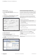
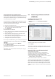
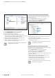
Table Of Contents
- Content
- 1 About this documentation
- 2 Safety
- 3 IO-Link overview
- 4 Module description
- 5 Assembly and installation
- 6 Commissioning
- 6.1 Requirements
- 6.2 Device description files
- 6.3 Procedure for commissioning
- 6.4 Commissioning with the SIMATIC Manager (PROFINET)
- 6.5 Commissioning with the TIA portal(PROFINET)
- 6.6 Commissioning with TwinCAT (EtherCAT)
- 6.7 Commissioning with Studio 5000(Ethernet/IP)
- 6.8 Commissioning with Automation Studio (POWERLINK)
- 6.9 Reading and writing data objects on IO-Link devices
- 6.10 “IO_LINK_CALL” function block
- 6.11 I&M functions
- 7 Planning IO-Link device configurations
- 8 Process data
- 9 Diagnostics and troubleshooting
- 10 Disassembly and disposal
6 Commissioning | “IO_LINK_CALL” function block
39Manual Communication module UR20-4COM-IO-LINK2547720000/03/09.2019
IO_LINK_CALL:outputparameters
Parameter Data type Description
DONE_VALID BOOL
Validity of data
0: Data invalid
1: Data valid
BUSY BOOL Read access / write access is executed
ERROR BOOL
0: no error
1: error and cancellation
STATUS DWORD Communication error message
IOL_STATUS DWORD IO-Link error message
RD_LEN DWORD Length of the data read
Processing of the function block lasts several PLC cycles.
The access, use of IO-Link port functions and the remaining
backup and recovery of device data must be controlled by
the user program.
SIEMENS offers the STEP7 IO-Link library for SIMATIC Man-
ager and the TIA Portal. In the more recent versions of the
IO-Link library, “IO_LINK_CALL” has been replaced by the
“IO_LINK_DEVICE” block.
Further information is available in the SIEMENS
document “Acyclic reading and writing with the
IO-Link library”.
You can download the SIEMENS IO-Link library
from the SIEMENS support website.
Reading and writing with “IO_LINK_DEVICE” in STEP7
You can read and write IO-Link device parameters using the
“IO_LINK_DEVICE” function block.
▶ Add the “IO_LINK_DEVICE” function block to the OB1 of
your user program.
▶ Create a new data block of type
ARRAY[0...231]ofBYTE.
This data block is the target range for data read and the
source range for data to be written.
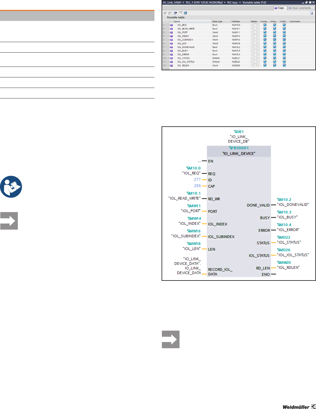
▶ Generate a new variable table for the input parameters
and output parameters of the function block.
Variable table for “IO_LINK_DEVICE” (TIA portal)
▶ Assign the variables to the inputs and outputs of the
function block.
You can enter the parameters ID and CAP directly on the
function block.
“IO_LINK_DEVICE” function block (TIA portal)
▶ Create a watch and force table with the input parameters
and output parameters of the function block.
▶ Force the variables for the input parameters to the
required values.
In the case of S7-300/400 CPUs, use the logical
start address of the module inputs as ID.
In the case of S7-1200/1500 CPUs, use the hard-
ware address of the module as ID.