
User Documentation
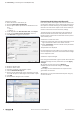
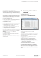
Table Of Contents
- Content
- 1 About this documentation
- 2 Safety
- 3 IO-Link overview
- 4 Module description
- 5 Assembly and installation
- 6 Commissioning
- 6.1 Requirements
- 6.2 Device description files
- 6.3 Procedure for commissioning
- 6.4 Commissioning with the SIMATIC Manager (PROFINET)
- 6.5 Commissioning with the TIA portal(PROFINET)
- 6.6 Commissioning with TwinCAT (EtherCAT)
- 6.7 Commissioning with Studio 5000(Ethernet/IP)
- 6.8 Commissioning with Automation Studio (POWERLINK)
- 6.9 Reading and writing data objects on IO-Link devices
- 6.10 “IO_LINK_CALL” function block
- 6.11 I&M functions
- 7 Planning IO-Link device configurations
- 8 Process data
- 9 Diagnostics and troubleshooting
- 10 Disassembly and disposal
6 Commissioning | Commissioning with Automation Studio (POWERLINK)
33Manual Communication module UR20-4COM-IO-LINK2547720000/03/09.2019
Integrating IO-Link device with Ethernet/IP
First set the process data length of the IO-Link master to the
required value. Setting the process data length requires that
the coupler is restarted. In doing so, the parameter settings
are reset to the factory settings.
An IO-Link device is integrated using the appropriate param-
eterisation of the associated IO-Link port. Use the u-remote
web server to parameterise IO-Link ports.
▶ Start the u-remote web server.
▶ In the station overview, click the IO-Link module to open
the component view of the IO-Link module.
▶ Click Parameter.
The parameters are displayed.
▶ Set the “Operating mode” parameter of the IO-Link port to
the value “IO-Link”.
▶ Set the “Process data length input” parameter of the
IO-Link port to the value “auto (default)”.
▶ Set the “Process data length output” parameter of the
IO-Link port to the value “auto (default)”.
▶ Change the other parameters as required.
Each change is labelled with a green symbol until it has been
applied. All changes are only saved when you click Apply
changes.
All changes are reset when you click Restore.
▶ Click Apply changes.
The changes are then transferred to the coupler and the
green labels are removed.
Alternatively, you can parameterise IO-Link ports using acy-
clic write accesses
6.8 Commissioning with Automation Studio
(POWERLINK)
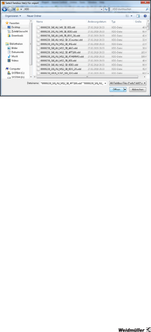
Installingthedevicedescriptionle
▶ Start Automation Studio.
▶ On the menu bar, click Tools/Import Fieldbus
Device....
▶ Select the directory where you have stored the device
description files.
Selecting XDD files
▶ Select the files that you would like to install.
▶ Click Open.
The hardware catalogue is updated automatically. The devic-
es from the current device description le are now listed in
the hardware catalogue.
Integrating IO-Link master with Automation Studio
▶ Start Automation Studio.
▶ Create a new project or open an existing project.
▶ Configure the control unit and the network as usual.
▶ Add the appropriate u-remote fieldbus coupler.
▶ Add the UR20-4COM-IO-LINK module from the hardware
catalogue to the u-remote station.
▶ Connect the fieldbus coupler to the controller.
The device description les support various congurations
for the UR20-4COM-IO-LINK module. The congurations
differ in terms of the process data length for the connected
IO-Link devices. The process data length you select should
only be as long as is required, in order to relieve the eldbus
system.