
User Documentation
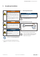
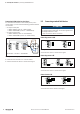
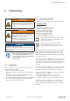
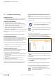
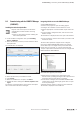
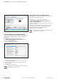
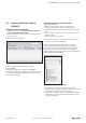
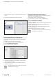
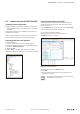
Table Of Contents
- Content
- 1 About this documentation
- 2 Safety
- 3 IO-Link overview
- 4 Module description
- 5 Assembly and installation
- 6 Commissioning
- 6.1 Requirements
- 6.2 Device description files
- 6.3 Procedure for commissioning
- 6.4 Commissioning with the SIMATIC Manager (PROFINET)
- 6.5 Commissioning with the TIA portal(PROFINET)
- 6.6 Commissioning with TwinCAT (EtherCAT)
- 6.7 Commissioning with Studio 5000(Ethernet/IP)
- 6.8 Commissioning with Automation Studio (POWERLINK)
- 6.9 Reading and writing data objects on IO-Link devices
- 6.10 “IO_LINK_CALL” function block
- 6.11 I&M functions
- 7 Planning IO-Link device configurations
- 8 Process data
- 9 Diagnostics and troubleshooting
- 10 Disassembly and disposal
6 Commissioning | Commissioning with Studio 5000 (Ethernet/IP)
30 2547720000/03/09.2019Manual Communication module UR20-4COM-IO-LINK
Integrating IO-Link device with TwinCAT
An IO-Link device is integrated using the appropriate parame-
terisation of the associated IO-Link port.
▶ Switch to Startup.
The current parameter setting is displayed.
You can edit the parameter setting.
▶ Double-click the parameter you want to edit.
The Edit dialogue box is opened.
Editing module parameters with TwinCAT
▶ Set the “Operating mode” parameter of the IO-Link port to
the value “IO-Link” (0x03).
▶ Set the “Process data length input” parameter to the
value “auto (default)” (0x21).
▶ Set the “Process data length output” parameter to the
value “auto (default)” (0x21).
▶ Change the other parameters as required.
All settings only take effect once they have been
loaded into the component.
6.7 Commissioning with Studio 5000
(Ethernet/IP)
Installingthedevicedescriptionles
▶ Start Studio 5000.
▶ Download and unzip the archive file from the Weidmüller
website.
▶ In the Tools menu within the Studio 5000 software,
select the EDS Hardware Installation Tool option.
▶ Follow the installation wizard.
Integrating IO-Link master with Studio 5000
▶ Start Studio 5000.
▶ Create a new project or open an existing project.
▶ Configure the control unit and the network as usual.
▶ Establish a connection to the controller (GoOnline).
If your project does not match the project on the controller,
load your project onto the controller (Download) or transfer
the project from the controller to Studio 5000 (Upload). The
controller must be in programming mode in both cases.
All projects downloaded from Studio 5000 to the
controller irrevocably overwrite any projects saved
on the controller.
▶ Add the u-remote station as usual.
The eldbus coupler and module are added with the stand-
ard process data width. Usually, this process data width does
not correspond with the existing IO-Link device congura-
tion.
You can adjust the process data length of the module to
your IO-Link device conguration using a sequence of acyclic
write operations. The following descriptions are examples of
the procedure with RSNetworx for EtherNet/IP. Alternatively,
you can implement the write operations with the MSG func-
tion component as generic CIP messages.
▶ Switch to RUN mode.
▶ Start RSNetworx for EtherNet/IP.
▶ Scan the network.
▶ Right-click the fieldbus coupler.
▶ In the context menu, click Class Instance Editor.
▶ Read the warning message and confirm by clicking on
Yes.
The Class Instance Editor is opened.