
User Documentation
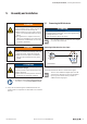
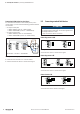
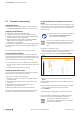
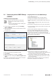
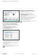
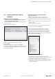
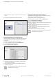
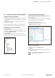
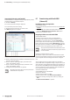
Table Of Contents
- Content
- 1 About this documentation
- 2 Safety
- 3 IO-Link overview
- 4 Module description
- 5 Assembly and installation
- 6 Commissioning
- 6.1 Requirements
- 6.2 Device description files
- 6.3 Procedure for commissioning
- 6.4 Commissioning with the SIMATIC Manager (PROFINET)
- 6.5 Commissioning with the TIA portal(PROFINET)
- 6.6 Commissioning with TwinCAT (EtherCAT)
- 6.7 Commissioning with Studio 5000(Ethernet/IP)
- 6.8 Commissioning with Automation Studio (POWERLINK)
- 6.9 Reading and writing data objects on IO-Link devices
- 6.10 “IO_LINK_CALL” function block
- 6.11 I&M functions
- 7 Planning IO-Link device configurations
- 8 Process data
- 9 Diagnostics and troubleshooting
- 10 Disassembly and disposal
6 Commissioning | Commissioning with the SIMATIC Manager (PROFINET)
25Manual Communication module UR20-4COM-IO-LINK2547720000/03/09.2019
6.4 Commissioning with the SIMATIC Manager
(PROFINET)
Installingthedevicedescriptionles
Projects must not be open in the hardware
conguration tool while the les are being
installed!
▶ Close any open projects before installing the
device description files!
▶ In the hardware configuration tool, open Installing
Extras / GSD files
▶ Select the directory in which you have stored the device
description files.
The available les are displayed.
Selecting the GSD(-ML) file
▶ Select the files that you would like to install.
▶ Click Install.
▶ When the installation is complete, click Close.
▶ Update the device catalogue via Extras / Update cata-
logue.
The devices associated with the current device description
le are now listed in the device catalogue.
Integrating IO-Link master with SIMATIC Manager
▶ Start SIMATIC Manager.
▶ Create a new project or open an existing project.
▶ Configure the controller and the network as usual.
▶ Add the appropriate u-remote fieldbus coupler to the sub-
net.
▶ In the hardware conguration tool, click the icon for the
eldbus coupler.
The module list is displayed in the lower part of the window.
▶ In the module list, click the slot to which you want to add
the IO-Link master.
The device description les support various congura-
tions for the UR20-4COM-IO-LINK module. The congu-
rations differ only in the length of the process data for the
IO-Link devices connected, e.g. 16bytes input data and
16bytes output data for IO-Link devices for the conguration
UR20-4COM-IOL-16BYTE-INOUT.
Select module with the appropriate process data length
▶ Determine the required process data length of the
IO-Link master, by adding the length of the input data and
output data of the IO-Link devices connected.
▶ In the device catalogue, select the UR20-4COM-IO-LINK
module with a process data length greater than or equal
to the required length.
▶ Double-click the module, or drag it into the module list.
The module is displayed in the module list.