
User Documentation
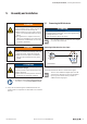
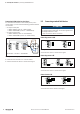
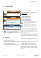
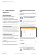
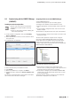
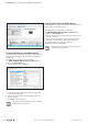
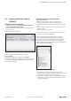
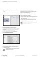
Table Of Contents
- Content
- 1 About this documentation
- 2 Safety
- 3 IO-Link overview
- 4 Module description
- 5 Assembly and installation
- 6 Commissioning
- 6.1 Requirements
- 6.2 Device description files
- 6.3 Procedure for commissioning
- 6.4 Commissioning with the SIMATIC Manager (PROFINET)
- 6.5 Commissioning with the TIA portal(PROFINET)
- 6.6 Commissioning with TwinCAT (EtherCAT)
- 6.7 Commissioning with Studio 5000(Ethernet/IP)
- 6.8 Commissioning with Automation Studio (POWERLINK)
- 6.9 Reading and writing data objects on IO-Link devices
- 6.10 “IO_LINK_CALL” function block
- 6.11 I&M functions
- 7 Planning IO-Link device configurations
- 8 Process data
- 9 Diagnostics and troubleshooting
- 10 Disassembly and disposal
6 Commissioning | Procedure for commissioning
24 2547720000/03/09.2019Manual Communication module UR20-4COM-IO-LINK
6.3 Procedure for commissioning
Updating the software
▶ Update the firmware of the fieldbus coupler and that of
the UR20-4COM-IO-LINK modules to the latest version.
ConguringtheIO-Linkmaster
▶ Install the current device description files.
▶ Configure the control unit and the network as usual.
▶ Add the required fieldbus coupler and the UR20-4COM-
IO-LINK module to your configuration.
▶ Adjust the process data length of the UR20-4COM-IO-
LINK module and the fieldbus coupler to your
IO-Link device configuration.
The procedure for adjusting the process data length depends
on which eldbus coupler and which engineering tool you
are using.
For commissioning examples, see sections 6.4 to 6.8.
Parameterising the IO-Link port
The IO-Link ports are parameterised via the parameters of
the IO-Link master. A eld device is integrated using the suit-
able parameterisation of the associated IO-Link port. An over-
view of all parameters can be found in section 4.6.
▶ For each IO-Link port, set the “Operating mode” parame-
ter such that the setting corresponds with the connected
device.
▶ Change the other parameters as required.
ConguringIO-Linkdevicesonline
You can use the u-remote IO-Link congurator to congure
the IO-Link system during ongoing operation.
▶ Start the u-remote IO-Link congurator.
▶ Establish a connection between the computer and the
u-remote station.
▶ Activate the IO-Link ports to which IO-Link devices are
connected.
▶ Assign the correct IODDs to these IO-Link ports.
▶ Parameterise the IO-Link devices.
▶ Write the edited parameters to the IO-Link devices.
You can nd further information on installation and opera-
tion of the u-remote IO-Link congurator in Chapter 7.
LoadingtheIO-Linkdevicecongurationtotheu-remote
station
You can load an exported IO-Link device configuration to the
u-remote station via the u-remote web server. This procedure
is suitable when you want to use the same configuration a
number of times.
▶ Always observe the complete documentation
in the u-remote web server manual
(document no. 2112220000).
If you access a eldbus coupler via the u-remote
IO-Link Congurator and the u-remote web server
simultaneously, this may result in access con-
icts.
▶ Start the u-remote web server.
▶ Open the component view of the IO-Link module by click-
ing on the IO-Link module in the station overview.
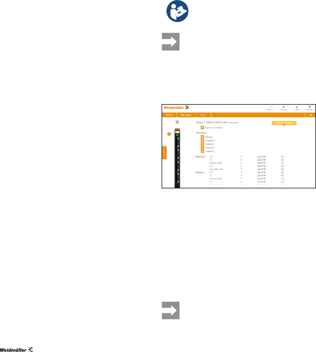
▶ In the component view, click Load device configura-
tion.
Loading the IO-Link device configuration to the u-remote station
▶ Select the required configuration file (.json) and click
Open.
A dialogue box with details for the IO-Link device congura-
tion is opened.
▶ Check whether the details for the IO-Link device configu-
ration correspond with the actual configuration.
▶ Click Upload.
The IO-Link device conguration is written to the module.
You can nd further information on installation and opera-
tion of the u-remote IO-Link congurator in Chapter 7.
You will receive an error message if the
IO-Link device conguration does not match the
connected IO-Link devices.