
User Documentation
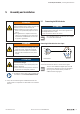
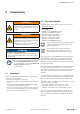
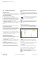
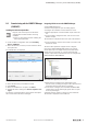
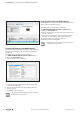
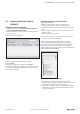
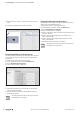
Table Of Contents
- Content
- 1 About this documentation
- 2 Safety
- 3 IO-Link overview
- 4 Module description
- 5 Assembly and installation
- 6 Commissioning
- 6.1 Requirements
- 6.2 Device description files
- 6.3 Procedure for commissioning
- 6.4 Commissioning with the SIMATIC Manager (PROFINET)
- 6.5 Commissioning with the TIA portal(PROFINET)
- 6.6 Commissioning with TwinCAT (EtherCAT)
- 6.7 Commissioning with Studio 5000(Ethernet/IP)
- 6.8 Commissioning with Automation Studio (POWERLINK)
- 6.9 Reading and writing data objects on IO-Link devices
- 6.10 “IO_LINK_CALL” function block
- 6.11 I&M functions
- 7 Planning IO-Link device configurations
- 8 Process data
- 9 Diagnostics and troubleshooting
- 10 Disassembly and disposal
6 Commissioning | Requirements
23Manual Communication module UR20-4COM-IO-LINK2547720000/03/09.2019
WARNUNG
Explosion risk!
▶ Before starting any work, make sure that
there is not a potentially explosive atmos-
phere!
WARNUNG!
Manipulation of the control unit!
During commissioning, the system may be
manipulated to such an extent that risk to life
and material damage can result.
▶ Make sure that system components can-
not start up unintentionally!
ATTENTION
The product can be destroyed!
▶ Perform an insulation test every time before putting the
station into operation (see section 7.6 in the u-remote
IP20 manual).
▶ Always observe the complete documentation
in the u-remote IP20 manual (document
no. 1432780000) and in the u-remote web
server manual (document no.
2112220000).
6.1 Requirements
Before you start the commissioning work, the following re-
quirements must be fullled.
– The control unit must be in operation.
– The u-remote station must be completely assembled and
wired.
– The fieldbus coupler and UR20-4COM-IO-LINK module
must use the current firmware versions.
– The control unit and u-remote station must be connected
to each other, and a PC/laptop must also be connected.
– The power supply must be turned on.
6.2 Devicedescriptionles
▶ Download the current device description files from the
Weidmüller website.
These include:
– GSDML files for PROFINET couplers
– GSD files for PROFIBUS couplers
– ESI files for EtherCAT couplers
– EDS files for Ethernet/IP couplers
– EDS files for DeviceNet couplers
– EDS files for CANopen couplers
– XDD files for POWERLINK couplers
If bitmap les for visualising the couplers are also
supplied, store them in the same folder as the
device description les.
You require the current device description
les in order to use all the functions of the
UR20-4COM-IO-LINK communication module.
The naming convention for GSDML les always follows this
pattern: GSDML_V2.3-WI-UR20-yyyymmdd.xml. The date
in the le name (dd.mm.yyyy) indicates the version of the
GSDML le and helps to determine whether you are already
using the latest version.
The version number of a GSD le can be found from the le.
If you open the le with a GSD editor, you can nd the ver-
sion number in the “Info_Text” entry. If you open the le with
a text editor, you can nd the version number in the entry
comment.
The version number of an ESI le can be found from the le.
If you open the le with a text editor, you can nd the version
number in the “FileVersion” attribute of the “Vendor” tag.
The version number of an EDS le can be found from the le.
Open the le using a text editor.
– Ethernet/IP: “Revision” entry in the “File” section
– DeviceNet: “Revision” entry in the “File” section
– CANopen: “FileVersion” entry in the “FileInfo” section
The version number of an XDD le can be found from the
le. If you open the le with a text editor, you can nd the
version number in the “FileVersion” attribute of the “Prole-
Body” tag.
6 Commissioning