
User Documentation
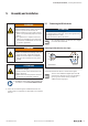
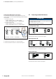
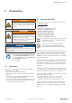
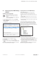
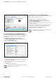
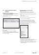
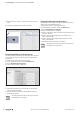
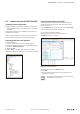
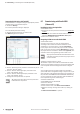
Table Of Contents
- Content
- 1 About this documentation
- 2 Safety
- 3 IO-Link overview
- 4 Module description
- 5 Assembly and installation
- 6 Commissioning
- 6.1 Requirements
- 6.2 Device description files
- 6.3 Procedure for commissioning
- 6.4 Commissioning with the SIMATIC Manager (PROFINET)
- 6.5 Commissioning with the TIA portal(PROFINET)
- 6.6 Commissioning with TwinCAT (EtherCAT)
- 6.7 Commissioning with Studio 5000(Ethernet/IP)
- 6.8 Commissioning with Automation Studio (POWERLINK)
- 6.9 Reading and writing data objects on IO-Link devices
- 6.10 “IO_LINK_CALL” function block
- 6.11 I&M functions
- 7 Planning IO-Link device configurations
- 8 Process data
- 9 Diagnostics and troubleshooting
- 10 Disassembly and disposal
5 Assemblyandinstallation | Connecting standard eld devices
22 2547720000/03/09.2019Manual Communication module UR20-4COM-IO-LINK
Connecting IO-Link device for class B port
To connect an IO-Link device with class B port to your u-
remote station, you also need the following potential distribu-
tion modules:
– for input current path
– UR20-16AUX-I (order no. 1334770000)
– UR20-16AUX-GND-I (order no. 1334800000)
– for output current path
– UR20-16AUX-O (order no. 1334780000)
– UR20-16AUX-GND-O (order no. 1334810000)
&4
/
/
',
/
/
&4
0
/
*1'
1
9'&
3
85&20,2/,1.85$8;[85$8;*1'[ ,2/LQNGHYLFH
Connecting IO-Link device for type B port
▶ Install the three modules in a u-remote station.
▶ Connect the IO-Link device as shown in the figure.
5.2 Connectingstandardelddevices
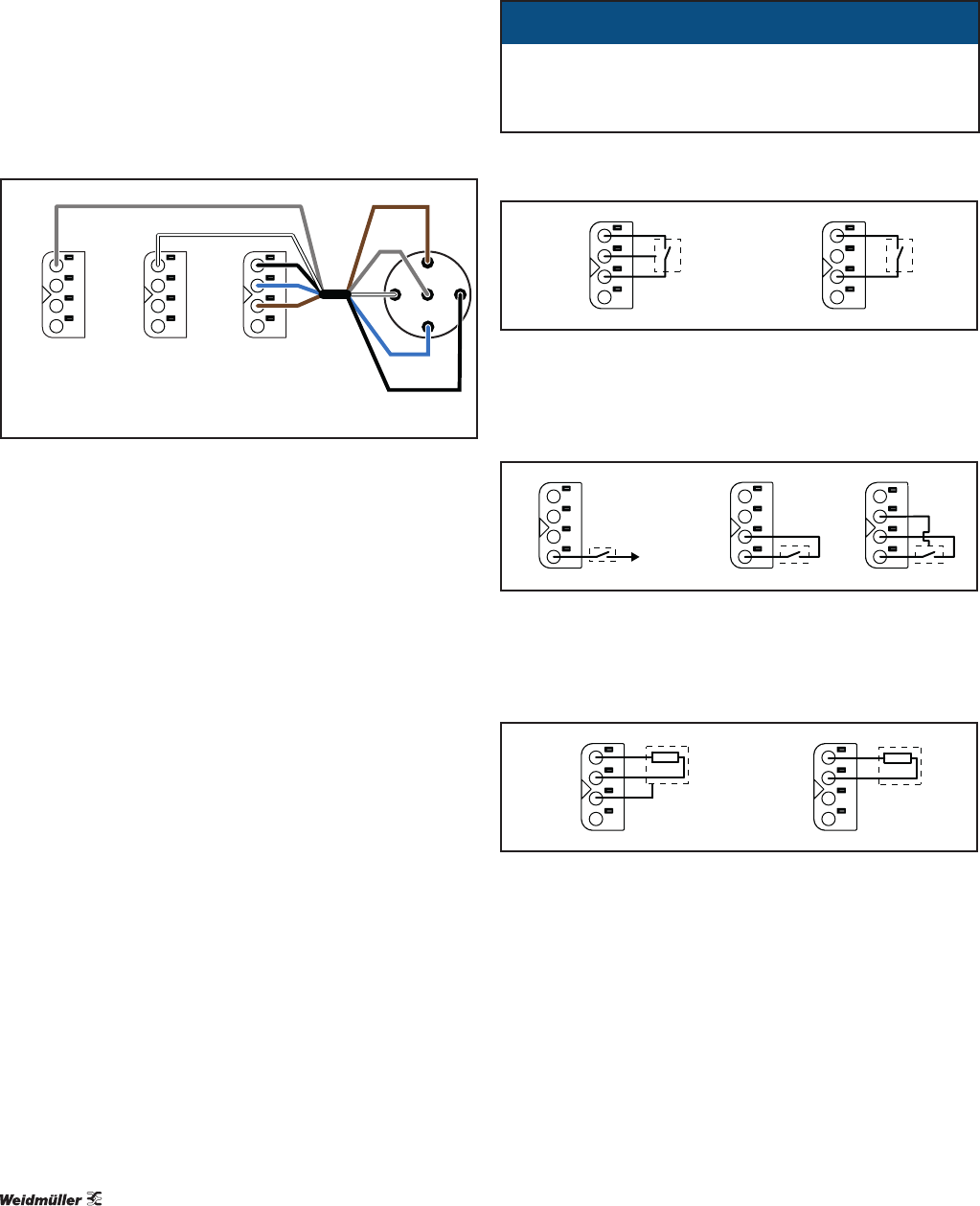
ATTENTION
The module can be destroyed!
The voltage between C/Q and L- must not be greater that
the voltage between L+ and L-.
▶ Only connect the devices as shown.
Connecting sensor to C/Q
&4
/
/
&4
/
Connecting sensor to C/Q
▶ Connect the sensor as shown in the figure.
Connecting sensor to DI
',
9'&
/
',
/
/
',
Connecting sensor to DI
▶ Connect the sensor as shown in the figure.
Connect load to C/Q
&4
/
/
&4
/
Connect load to C/Q
▶ Connect the load as shown in the figure.