
User Documentation
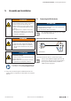
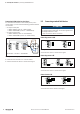
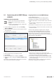
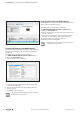
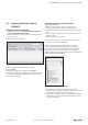
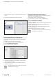
Table Of Contents
- Content
- 1 About this documentation
- 2 Safety
- 3 IO-Link overview
- 4 Module description
- 5 Assembly and installation
- 6 Commissioning
- 6.1 Requirements
- 6.2 Device description files
- 6.3 Procedure for commissioning
- 6.4 Commissioning with the SIMATIC Manager (PROFINET)
- 6.5 Commissioning with the TIA portal(PROFINET)
- 6.6 Commissioning with TwinCAT (EtherCAT)
- 6.7 Commissioning with Studio 5000(Ethernet/IP)
- 6.8 Commissioning with Automation Studio (POWERLINK)
- 6.9 Reading and writing data objects on IO-Link devices
- 6.10 “IO_LINK_CALL” function block
- 6.11 I&M functions
- 7 Planning IO-Link device configurations
- 8 Process data
- 9 Diagnostics and troubleshooting
- 10 Disassembly and disposal
5 Assemblyandinstallation | Connecting the IO-Link device
21Manual Communication module UR20-4COM-IO-LINK2547720000/03/09.2019
WARNING
Explosion risk!
During installation work, sparks can form and
surfaces may become excessively hot
▶ Before starting any work, make sure that
there is not a potentially explosive atmos-
phere!
▶ For applications in explosive risk zones,
observe the installation and construction
requirements of EN60079-15 and coun-
try-specific regulations.
WARNING
Dangerous contact voltage!
▶ Carry out assembly and wiring work only
when the power supply disconnected.
▶ Make sure that the place of installation
has been disconnected from the power
supply!
ATTENTION
The product can be destroyed by elec-
trostatic discharge!
u-remote products can be destroyed by elec-
trostatic discharge.
▶ Please make sure that persons and work
equipment are adequately earthed!
▶ In addition, always refer to the complete doc-
umentation in the u-remote IP20 manual.
▶ Carry out all work during the installation/removal and
replacement of components as described in the u-remote
manual.
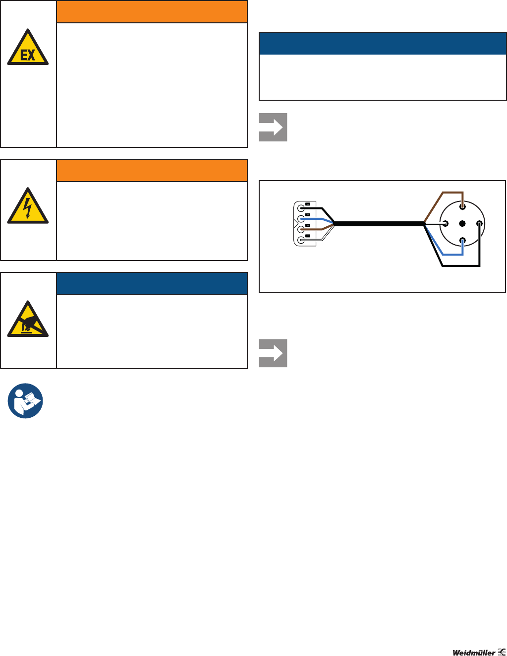
5.1 Connecting the IO-Link device
ATTENTION
The module can be destroyed!
The voltage between C/Q and L- must not be greater that
the voltage between L+ and L-.
▶ Only connect the devices as shown.
Use unshielded cables of maximum 20 m length
to connect IO-Link devices.
Connecting IO-Link device for class A port
&4
/
/
',
/
/
&4
',
85&20,2/,1. ,2/LQNGHYLFH
Connecting IO-Link device for class A port (DI connection optional)
▶ Connect the IO-Link device as shown in the figure.
The use of the additional digital input at the DI
connection is optional. You can use this digital
input, e.g. if the IO-Link device provides an
additional switching signal.
5 Assembly and installation