
User Documentation
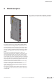
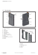
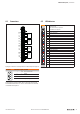
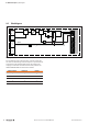

Table Of Contents
- Content
- 1 About this documentation
- 2 Safety
- 3 IO-Link overview
- 4 Module description
- 5 Assembly and installation
- 6 Commissioning
- 6.1 Requirements
- 6.2 Device description files
- 6.3 Procedure for commissioning
- 6.4 Commissioning with the SIMATIC Manager (PROFINET)
- 6.5 Commissioning with the TIA portal(PROFINET)
- 6.6 Commissioning with TwinCAT (EtherCAT)
- 6.7 Commissioning with Studio 5000(Ethernet/IP)
- 6.8 Commissioning with Automation Studio (POWERLINK)
- 6.9 Reading and writing data objects on IO-Link devices
- 6.10 “IO_LINK_CALL” function block
- 6.11 I&M functions
- 7 Planning IO-Link device configurations
- 8 Process data
- 9 Diagnostics and troubleshooting
- 10 Disassembly and disposal

4 Moduledescription | Editable parameters
19Manual Communication module UR20-4COM-IO-LINK2547720000/03/09.2019
“Channel diagnostics” parameter
The “Channel diagnostics” parameter activates channel diag-
nostics.
Disabled (default)
Channel diagnostics is disabled.
Enabled
Channel diagnostics is enabled.
“Process data length input” parameter
The “Process data length input” parameter denes how
many bytes the process input data of the IO-Link master are
occupied by the cyclic input data of the IO-Link device con-
nected.
0…32bytes
The cyclic input data of the IO-Link device connected occu-
pies 0…32 bytes of the IO-Link master process input data.
auto (default)
The length of the cyclic input data is automatically set to the
IO-Link device connected.
“Process data length output” parameter
The “Process data length output” parameter denes how
many bytes of the IO-Link master process output data are oc-
cupied by the cyclic data of the IO-Link device connected.
0…32bytes
The cyclic output data of the IO-Link device connected occu-
pies 0…32 bytes of the IO-Link master process output data.
auto (default)
The length of the cyclic output data is automatically set to
match the IO-Link device connected.