
User Documentation
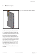
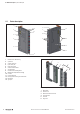
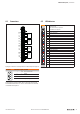
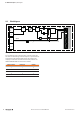
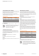
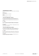

Table Of Contents
- Content
- 1 About this documentation
- 2 Safety
- 3 IO-Link overview
- 4 Module description
- 5 Assembly and installation
- 6 Commissioning
- 6.1 Requirements
- 6.2 Device description files
- 6.3 Procedure for commissioning
- 6.4 Commissioning with the SIMATIC Manager (PROFINET)
- 6.5 Commissioning with the TIA portal(PROFINET)
- 6.6 Commissioning with TwinCAT (EtherCAT)
- 6.7 Commissioning with Studio 5000(Ethernet/IP)
- 6.8 Commissioning with Automation Studio (POWERLINK)
- 6.9 Reading and writing data objects on IO-Link devices
- 6.10 “IO_LINK_CALL” function block
- 6.11 I&M functions
- 7 Planning IO-Link device configurations
- 8 Process data
- 9 Diagnostics and troubleshooting
- 10 Disassembly and disposal
4 Moduledescription | Device description
12 2547720000/03/09.2019Manual Communication module UR20-4COM-IO-LINK
4.1 Device description
Communication module UR20-4COM-IO-LINK
1 Release lever for DIN rail fixing
2 System bus
3 System current path
4 Input current path
5 Output current path
6 Seats for module markers
7 Type designation
8 Connector frame unlocking device
9 Module status LED (collective message)
10 Connector
11 Channel status LED
12 Latching hook for latching onto module sides
13 DIN rail foot
14 Type plate
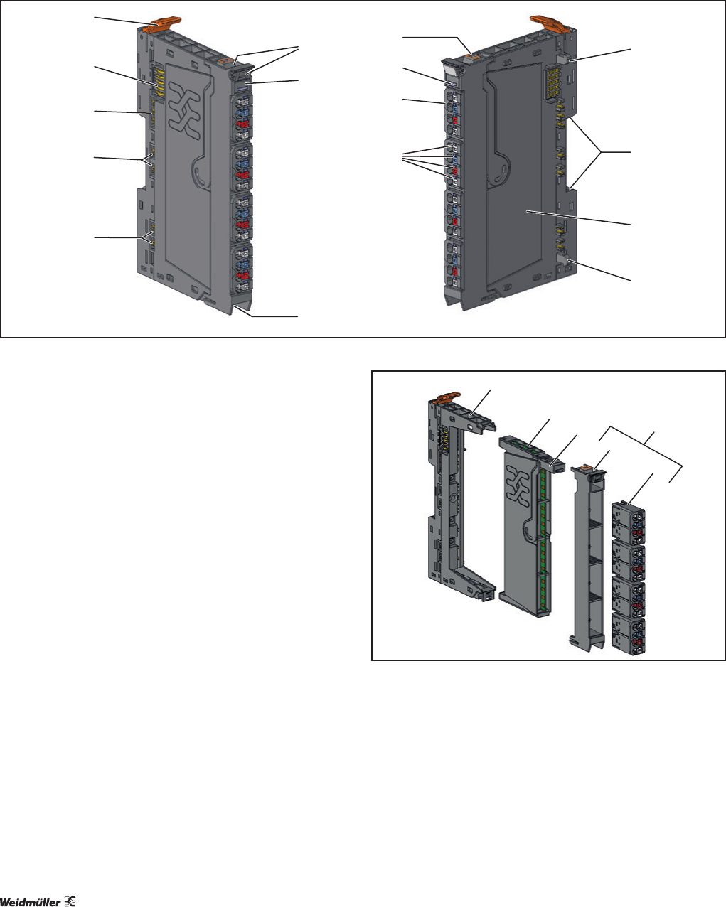
I/O-Module components
1 Base module
2 Electronic unit
3 Removal lever for electronic unit
4 Connector frame
5 Connector
6 Plug-in unit