
User Documentation
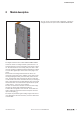
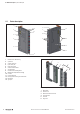
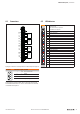
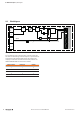
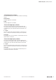

Table Of Contents
- Content
- 1 About this documentation
- 2 Safety
- 3 IO-Link overview
- 4 Module description
- 5 Assembly and installation
- 6 Commissioning
- 6.1 Requirements
- 6.2 Device description files
- 6.3 Procedure for commissioning
- 6.4 Commissioning with the SIMATIC Manager (PROFINET)
- 6.5 Commissioning with the TIA portal(PROFINET)
- 6.6 Commissioning with TwinCAT (EtherCAT)
- 6.7 Commissioning with Studio 5000(Ethernet/IP)
- 6.8 Commissioning with Automation Studio (POWERLINK)
- 6.9 Reading and writing data objects on IO-Link devices
- 6.10 “IO_LINK_CALL” function block
- 6.11 I&M functions
- 7 Planning IO-Link device configurations
- 8 Process data
- 9 Diagnostics and troubleshooting
- 10 Disassembly and disposal
4 Moduledescription
11Manual Communication module UR20-4COM-IO-LINK2547720000/03/09.2019
Digital communication module UR20-4COM-IO-LINK (order no. 1315740000)
The digital communication module UR20-4COM-IO-LINK is
an IO-Link master according to IO-Link specication V1.1.2.
One IO-Link device can be connected to each plug-in connec-
tor. The IO-Link devices must comply with port class A. Port
class B is possible if additional potential distribution modules
are used. One digital input can be used at each plug-in con-
nector.
Process data is exchanged with the IO-Link device con-
nected via each IO-Link port. In addition, acyclic data can be
exchanged (diagnosis data, parameter data, status informa-
tion). The parameter data of the IO-Link devices connected
can be stored in the master module where they are managed
from a parameterising server (Data Storage). This means that
the IO-Link master or an IO-Link device (from IO-Link speci-
cation version1.1) are very easy to replace.
The four communication channels can also be used as digi-
tal inputs or outputs with standard eld devices.
A status LED is assigned to each channel. The module elec-
tronics supply the connected sensors with power from the
input current path (I
IN
).
The inputs are protected against voltage surges and overcur-
rent. Voltages that exceed ± 30V may cause the destruction
of the module.
You can use the “u-remote IO-Link congurator” software to
congure the IO-Link system for the UR20-4COM-IO-LINK.
4 Module description