Remote-I/O-System u-remote UR20 Communication module UR20-4COM-IO-LINK Manual Letʼs connect.
Content 1 1.1 1.2 1.3 1.4 About this documentation Symbols and notes Complete documentation Standard data structure Software releases described 3 3 3 4 4 2 2.1 2.2 2.3 2.4 Safety General safety notice Intended use Use in a potentially explosive atmosphere Legal notice 5 5 6 6 7 3 IO-Link overview 9 4 4.1 4.2 4.3 4.4 4.5 4.6 Module description Device description Connections LED indicators Block diagram Technical data Editable parameters 11 12 13 13 14 15 17 5 5.1 5.
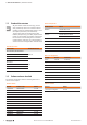
1 About this documentation | Symbols and notes 1 About this documentation 1.1 Symbols and notes The situation-dependent safety notices may contain the following warning symbols: The safety notices in this documentation are designed according to the severity of the danger. Symbol DANGER Imminent danger to life! Notes with the signal word “Danger” warn you of situations that will result in serious injury or death if you do not follow the instructions given in this manual.
1 About this documentation | Standard data structure 1.3 Standard data structure All given details of data structure (e.g. process data, parameters) refer to the u-remote internal mapping, when the standard data format is set in the coupler parameters (see table below). The way these data are represented by other fieldbus participants (e.g. the PLC), depends additionally on the fieldbus specification and the data format of the communicating device.
2 Safety | General safety notice 2 Safety This chapter includes general safety instructions for handling the communication module UR20-4COM-IO-LINK. Specific warning notices for specific tasks and situations are given at the appropriate places in the documentation. Failure to observe the safety and warning notices can result in damage to persons and material. This manual contains product-specific information and notes about the communication module UR20-4COM-IO-LINK.
2 Safety | Intended use Shielding IO-Link Devices and conventional sensors/actuators are connected to the UR20-4COM-IO-LINK communication module via unshielded cables. 2.2 Intended use The UR20-4COM-IO-LINK communication module is an I/O module from the u-remote series. It is intended for use in a u-remote station. As an IO-Link master the module can integrate up to four IO-Link Devices in an automation system. The products of the u-remote series are intended for use in industrial automation.
2 Safety | Legal notice 2.4 Legal notice The communication module UR20-4COM-IO-LINK is CEcompliant in accordance with Directive 2014/30/EU (EMC Directive). It also meets the requirements of the ATEX Directive 2014/34/EU. The results of the measurements according to CISPR 16-23 should also be suitable to demonstrate the compliance of the u-remote devices to the limits for radiated emissions as defined by CFR 47 Part 15, Subpart B, §15.109, Class A (2010) and ICES-003, Issue 5, Class A (2012).
Manual Communication module UR20-4COM-IO-LINK 2547720000/03/09.
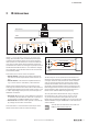
3 IO-Link overview 3 IO-Link overview ,QGXVWULDO (WKHUQHW )LHOGEXV PDVWHU PDVWHU IO-Link for automation technology IO-Link is a communication protocol for automation technology. IO-Link enables serial, bi-directional point-to-point communication between devices on the sensor-actuator level and devices on the field level or control level. Besides cyclic process data, IO-Link allows parameters, diagnoses and identification data to be exchanged acyclically.
Manual Communication module UR20-4COM-IO-LINK 2547720000/03/09.
4 Module description 4 Module description You can use the “u-remote IO-Link configurator” software to configure the IO-Link system for the UR20-4COM-IO-LINK. Digital communication module UR20-4COM-IO-LINK (order no. 1315740000) The digital communication module UR20-4COM-IO-LINK is an IO-Link master according to IO-Link specification V1.1.2. One IO-Link device can be connected to each plug-in connector. The IO-Link devices must comply with port class A.
4 Module description | Device description 4.
4 Module description | Connections 4.2 Connections 4.3 LED indicators Module status LED Green: Communication on system bus Red: Collective error diagnostic 4 IO LINK 4 IO LINK C/Q 1 L– 1 L+ 1 DI 1 C/Q 2 L– 2 L+ 2 DI 2 C/Q 3 L– 3 L+ 3 DI 3 C/Q 4 L– 4 L+ 4 DI 4 1 2 1 IO-LINK Device 3 4 1 2 2 IO-LINK Device 3 4 1 2 3 IO-LINK Device 3 4 Yellow: Status COM 1 1.2 Red: Error IO-Link port 1 1.4 Yellow: Status DI 1 2.1 Yellow: Status COM 2 2.2 Red: Error IO-Link port 2 2.
4 Module description | Block diagram 4.4 Block diagram µC System bus USYS UIN 4x µC GND GND IN 24 V DC IN UOUT 1 C/Q 1 L– 1 L+ 1 DI 1 2 C/Q 2 L– 2 L+ 2 DI 2 3 C/Q 3 L– 3 L+ 3 DI 3 4 C/Q 4 L– 4 L+ 4 DI 4 Block diagram UR20-4COM-IO-LINK The numbering of the channels in the u-remote system differs from the numbering of the IO-Link port as per the IO-Link specification.
4 Module description | Technical data 4.5 Technical data UR20-4COM-IO-Link System data Data (coupler dependent) see Chapter 8 Interface u-remote system bus System bus transfer rate 48 MBit/s Digital inputs Number 4 Sensor types Typ 1 and Typ 3 acc.
4 Module description | Technical data UR20-4COM-IO-Link Flammability rating UL 94 V-0 Temperature data Operation -20 °C ... +60 °C / - 4 ... +140 °F Storage, transport -40 °C ... +85 °C / - 40 ...
4 Module description | Editable parameters 4.6 Editable parameters Overview of the editable parameter UR20-4COM-IO-LINK Channel Description Options1 Default 0 ... 3 Operating mode disabled (0) / DO (1) / DI (2) / IO-Link (3) disabled 0 ... 3 Port cycle Free running (0) / Fixed cycle (1) / Message sync (2) Free running 0 ... 3 Port cycle time [n*0.1 ms] 4 ... 1326 4 0 ... 3 IO-Link device check disabled (0) / Type compare (1) / Identical (2) disabled 0 ...
4 Module description | Editable parameters “Port cycle time (n*0.1 ms)” parameter The “Port cycle time (n*0.1 ms)” defines the cycle time of the IO-Link port. This parameter is only relevant if the “Port cycle” parameter has been set to “Fixed value”. According to the IO-Link specification, the cycle time is coded with a time base (2 bits) and a multiplier (6 bits). The coding is dependent on the cycle time. Coding the cycle time Cycle time Time base Multipl. Calculation 0,4 ms ... 6,3 ms 0,1 ms 4 ..
4 Module description | Editable parameters “Channel diagnostics” parameter The “Channel diagnostics” parameter activates channel diagnostics. Disabled (default) Channel diagnostics is disabled. Enabled Channel diagnostics is enabled. “Process data length input” parameter The “Process data length input” parameter defines how many bytes the process input data of the IO-Link master are occupied by the cyclic input data of the IO-Link device connected.
Manual Communication module UR20-4COM-IO-LINK 2547720000/03/09.
5 Assembly and installation | Connecting the IO-Link device 5 Assembly and installation 5.1 WARNING Explosion risk! During installation work, sparks can form and surfaces may become excessively hot ▶▶ Before starting any work, make sure that there is not a potentially explosive atmosphere! ▶▶ For applications in explosive risk zones, observe the installation and construction requirements of EN 60079-15 and country-specific regulations.
5 Assembly and installation | Connecting standard field devices Connecting IO-Link device for class B port To connect an IO-Link device with class B port to your uremote station, you also need the following potential distribution modules: –– for input current path –– UR20-16AUX-I (order no. 1334770000) –– UR20-16AUX-GND-I (order no. 1334800000) –– for output current path –– UR20-16AUX-O (order no. 1334780000) –– UR20-16AUX-GND-O (order no.
6 Commissioning | Requirements 6 Commissioning 6.2 WARNUNG Explosion risk! ▶▶ Before starting any work, make sure that there is not a potentially explosive atmosphere! WARNUNG! Manipulation of the control unit! During commissioning, the system may be manipulated to such an extent that risk to life and material damage can result.
6 Commissioning | Procedure for commissioning 6.3 Loading the IO-Link device configuration to the u-remote station Procedure for commissioning Updating the software ▶▶ Update the firmware of the fieldbus coupler and that of the UR20-4COM-IO-LINK modules to the latest version. Configuring the IO-Link master ▶▶ Install the current device description files. ▶▶ Configure the control unit and the network as usual. ▶▶ Add the required fieldbus coupler and the UR20-4COMIO-LINK module to your configuration.
6 Commissioning | Commissioning with the SIMATIC Manager (PROFINET) 6.4 Commissioning with the SIMATIC Manager Integrating IO-Link master with SIMATIC Manager (PROFINET) ▶▶ Start SIMATIC Manager.
6 Commissioning | Commissioning with the SIMATIC Manager (PROFINET) Integrating IO-Link device with SIMATIC Manager An IO-Link device is integrated using the suitable parameterization of the associated IO-Link port. ▶▶ Double-click the module in the module list. The UR20-4COM-IO-LINK Properties window opens. ▶▶ Select the Parameters tab. ▶▶ Set the “Operating mode” parameter of the IO-Link port to the value “IO-Link”.
6 Commissioning | Commissioning with the TIA portal (PROFINET) 6.5 Commissioning with the TIA portal (PROFINET) Installing the device description files ▶▶ In the project view, open: Extras / Manage general station description files (GSD) ▶▶ Select the directory in which you have stored the device description files. The available files are displayed. Integrating IO-Link master with the TIA portal ▶▶ Start the TIA portal. ▶▶ Create a new project or open an existing project.
6 Commissioning | Commissioning with the TIA portal(PROFINET) ▶▶ Double-click the module, or drag it into the device overview. The module is displayed in the device overview. Integrating IO-Link device with the TIA portal A IO-Link device is integrated using the suitable parameterization of the associated IO-Link port. ▶▶ Select the module in the device overview. ▶▶ In the inspection window, select the General tab. ▶▶ Select Component parameters. The list of all parameters is displayed.
6 Commissioning | Commissioning with TwinCAT (EtherCAT) 6.6 Commissioning with TwinCAT (EtherCAT) Installing the device description files ▶▶ Before starting TwinCAT, copy the ESI files to the TwinCAT installation folder, e.g. C:\TwinCAT\3.1\Config\Io\ EtherCAT. Existing folder structures in the ESI files must remain unchanged when copying. After starting TwinCAT 3, the devices from the device description files are available in the hardware catalogue.
6 Commissioning | Commissioning with Studio 5000 (Ethernet/IP) Integrating IO-Link device with TwinCAT An IO-Link device is integrated using the appropriate parameterisation of the associated IO-Link port. ▶▶ Switch to Startup. The current parameter setting is displayed. You can edit the parameter setting. ▶▶ Double-click the parameter you want to edit. The Edit dialogue box is opened. 6.7 Commissioning with Studio 5000 (Ethernet/IP) Installing the device description files ▶▶ Start Studio 5000.
6 Commissioning | Commissioning with Studio 5000(Ethernet/IP) Change the length of the input data for the module: ▶▶ Select the service code “Set Single Attribute” (10) ▶▶ Set the object address parameter as hexadecimal numbers. –– Class: 67 (module parameters) –– Instance: slot of the UR20-4COM-IO-LINK module –– Attribute: 65 (length of the input data) ▶▶ In the drop-down list Transmit data size, select Byte.
6 Commissioning | Commissioning with Studio 5000(Ethernet/IP) Restart the coupler: ▶▶ Select the service code “Reset” (5). ▶▶ Deactivate Send the attribute ID. ▶▶ Set the object address parameter as hexadecimal numbers. –– Class: 1 –– Instance: 1 ▶▶ In the drop-down list Transmit data size, select Byte. ▶▶ In the text field Data sent to the device, enter “0”. ▶▶ Click Execute to trigger the transaction.
6 Commissioning | Commissioning with Automation Studio (POWERLINK) Integrating IO-Link device with Ethernet/IP 6.8 An IO-Link device is integrated using the appropriate parameterisation of the associated IO-Link port. Use the u-remote web server to parameterise IO-Link ports. ▶▶ Start Automation Studio. ▶▶ On the menu bar, click Tools/Import Fieldbus Device.... ▶▶ Select the directory where you have stored the device description files.
6 Commissioning | Commissioning with Automation Studio (POWERLINK) Parameterising IO-Link port with Automation Studio The IO-Link ports are parameterised via the parameters of the IO-Link master. An overview of all parameters can be found in section 4.6. ▶▶ In the Physical View, right-click the module. ▶▶ In the context menu, click Configuration. The list of all parameters is displayed. Restarting the coupler ▶▶ In the Physical View, right-click the module. ▶▶ Click Configuration in the context menu.
6 Commissioning | Reading and writing data objects on IO-Link devices FB_M FBC/IO-M data / with data write.req acyclic-write.res If you want to read and write IO-Link data objects only during commissioning, we recommend using the IO-Link Configurator (see Chapter 7). The client application then performs a sequence of read accesses (acyclic-read.req).
6 Commissioning | Reading and writing data objects on IO-Link devices Addresses for acyclic accesses Acyclic write access: Addressing the requests (.req) Protocol Address PROFIBUS 227 or 255 PROFINET 227 (0x00E3) CANopen 0x2200:0 MODBUS-TCP 0x2C00 - 2C7F EtherCAT 0x4020:1 Ethernet/IP Class 0x64, Instance 1, Attribute 0x78 DeviceNet Class 0x64, Instance 1, Attribute 0x78 POWERLINK 0x2200:0 IO-Link Call IO-Link data objects and IO-Link port functions are accessed via IO-Link Call.
6 Commissioning | Reading and writing data objects on IO-Link devices Reading out device information Reading out process data mapping Read out device information: Request Length Data object Description [bytes] Read out process data mapping: Request Length Data object Description [bytes] You can read out device information of connected IO-Link devices. You can read out the process data mapping of an IO-Link master (details in bytes).
6 Commissioning | “IO_LINK_CALL” function block Reading out the event queue 6.10 “IO_LINK_CALL” function block Read out event queue: Request Length Data object Description [bytes] The “IO_LINK_ CALL” function block allows acyclic communication with an IO-Link device: device parameters are written and parameters, measured values and diagnostic data are read. You can read out events from the event queue.
6 Commissioning | “IO_LINK_CALL” function block IO_LINK_CALL: output parameters Parameter Data type Description DONE_VALID BOOL BUSY BOOL ERROR BOOL STATUS DWORD IOL_STATUS DWORD IO-Link error message RD_LEN DWORD Length of the data read Validity of data 0: Data invalid 1: Data valid Read access / write access is executed 0: no error 1: error and cancellation Communication error message Processing of the function block lasts several PLC cycles.
6 Commissioning | I&M functions For PORT, use the number of the IO-Link port, not the number of the channel. ▶▶ Generate a rising edge at REQ to start the data transmission. Processing of the function block takes several PLC cycles. During processing, the BUSY output is on 1. After successful processing, the BUSY output switches to 0. The DONE_VALID output switches to 1. During read access, the data read is displayed in the data block. 6.
7 Planning IO-Link device configurations | u-remote IO-Link configurator 7 Planning IO-Link device configurations 7.1 u-remote IO-Link configurator 7.3 You can use the u-remote IO-Link configurator to configure the IO-Link system. You can carry out the following functions for test purposes, during commissioning or service work: –– Create and export IO-Link device configurations. –– Parameterise IO-Link devices during ongoing operation.
7 Planning IO-Link device configurations | Operating the u-remote IO-Link configurator IO-Link device detailed view 1 1 6 2 2 7 3 6 7 8 8 3 4 9 10 11 9 5 4 IO-Link port overview (offline mode) 1 2 3 4 5 6 7 8 9 5 Displaying the starting page Opening the IODDfinder in the standard browser Adding IODD to IO-Link port Parameterising the IO-Link device Deleting IODD from IO-Link port Changing the language Connecting to the fieldbus coupler Reading out the process data length of the configura
7 Planning IO-Link device configurations | Operating the u-remote IO-Link configurator Creating a new project Opening the IODDfinder in the standard browser ▶▶ Navigate to the IO-Link port overview. ▶▶ Open the context menu. ▶▶ Click Create new. ▶▶ If you wish to discard the existing project, click OK. To add an IO-Link device to a configuration, you will need the relevant IODD from the manufacturer. You can search for and download IODDs using the IODDfinder.
7 Planning IO-Link device configurations | Editing IO-Link device configurations 7.4 Editing IO-Link device configurations Removing the IO-Link device assignment Assigning the IO-Link device to an IO-Link port Deleting the IO-Link device Adding an IODD ▶▶ Navigate to the IO-Link port overview. ▶▶ For the empty IO-Link port, click Select IODD, in order to add the IODD. ▶▶ Select the IODD of the IO-Link device (.zip, .xml). ▶▶ Click Open. Some IODDs describe several device types.
7 Planning IO-Link device configurations | Editing IO-Link device configurations online Finding and rectifying parameter errors Faulty parameterised IO-Link devices are indicated by a red frame around the IO-Link port concerned. 7.5 Editing IO-Link device configurations online WARNING! Manipulation of the control unit! During commissioning, the system may be manipulated to such an extent that this can result in risks to life and material damage.
7 Planning IO-Link device configurations | Editing IO-Link device configurations online Activating an IO-Link port You must be connected to the fieldbus coupler. The Configurator calls up the identification data of the IO-Link device and illustrates it in the IO-Link port overview. If you have already assigned an IO-Link device to this IO-Link port, the Configurator compares the identification data of the IODD with the identification data of the connected IO-Link device. Matches are highlighted in green.
7 Planning IO-Link device configurations | Editing IO-Link device configurations online If you want to update all parameters in a section: ▶▶ Click the update icon next to the section heading. Displaying process data If you want to update all parameters of an IO-Link device: ▶▶ Open the context menu. ▶▶ Click Read all parameters. ▶▶ In the device tree, switch to the required IO-Link master. ▶▶ In the IO-Link port overview, click Show process data.
Manual Communication module UR20-4COM-IO-LINK 2547720000/03/09.
8 Process data | Process data mapping 8 Process data 8.1 Process data mapping 3URFHVV GDWD PRGXOH %\WH 3URFHVV GDWD ,2 /LQN GHYLFHV %\WH 3URFHVV GDWD RXWSXWV 3URFHVV GDWD LQSXWV 2% ,% 2% ,% 2% ,% 2% ,% 2% ,% 2% ,% 2% ,% 2% ,% 2% ,% 2% ,% 2% ,% 2% ,% 2% ,% 2% ,% 2% ,% 2% ,% 2% ,% 2% ,% ,2 /LQN GHYLFH ,2 /LQN SRUW 3URFHVV GDWD OHQJWK ,QSXW %\WH 3URFHVV GDWD OHQJWK 2XWSXW %\WH ,2 /LQN GHYLFH ,2 /L
8 Process data | Process input data 8.2 Process input data 8.3 Process data inputs UR20-4COM-IO-LINK Byte 50 Bit IX0.0 IX0.1 IX0.2 IX0.3 IX0.4 IX0.5 IX0.6 IX0.7 IX1.0 IX1.1 IX1.2 IX1.3 IX1.4 IX1.5 IX1.6 IX1.7 Process output data Process data outputs UR20-4COM-IO-LINK Description Byte Bit OX0.0 OX0.1 OX0.2 OX0.3 OX0.4 OX0.5 OX0.6 OX0.7 OX1.0 OX1.1 OX1.2 OX1.3 OX1.4 OX1.5 OX1.6 OX1.
8 Process data | Fieldbus-dependent process data widths 8.4 Fieldbus-dependent process data widths The following tables show which process data lengths are available for the individual couplers, and the relevant fieldbus-dependent data widths. UR20-FBC-PB-DP Process data for IO-Link devices Fieldbus dependent data widths1) Input Output Input Output Byte Byte Byte Byte 4 4 6 6 8 8 10 10 16 16 18 18 32 32 34 34 16 8 18 10 32 16 34 18 32 8 34 10 1) incl.
8 Process data | Fieldbus-dependent process data widths UR20-FBC-EC With EtherCAT, configurable data widths are not supported. Process data for IO-Link devices Fieldbus dependent data widths Input Output Input Output Byte Byte Byte Byte 16 16 19 18 1) 1) incl. 2 Byte module process data UR20-FBC-MOD-TCP, UR20-FBC-MOD-TCP-V2 You can select the length of the process input data and the length of the process output data independently of each other.
8 Process data | Fieldbus-dependent process data widths UR20-FBC-EIP You can select the length of the process input data and the length of the process output data independently of each other. Process data for IO-Link devices Fieldbus dependent data widths1) Input Output Input Output Byte Byte Byte Byte 0 ... 128 0 ... 128 2 ... 130 2 ... 130 1) incl.
Manual Communication module UR20-4COM-IO-LINK 2547720000/03/09.
9 Diagnostics and troubleshooting | Diagnostic data 9 Diagnostics and troubleshooting 9.1 Diagnostic data Diagnostic data UR20-4COM-IO-LINK Channel diagnoses can be activated with the “Channel diagnosis” parameter. Diagnostic data UR20-4COM-IO-LINK Name Byte Error indicator 0 Module type 1 Error byte 2 2 Error byte 3 3 Channel type Diagnostic bits per channel Number of channels Channel error 4 Bit 0 1 2 3 4 5 6 7 0 1 2 3 4 5 6 7 0 ... 7 0 ...
9 Diagnostics and troubleshooting | LED indicators and troubleshooting 9.3 LED indicators and troubleshooting LED Status Status LED Channel LED 56 Red: 1.1 ... 4.1 1.2 ...4.2 Yellow: Red: –– –– –– –– –– –– 1.4 ... 4.4 Yellow: –– Status DI 1 ... DI 4 Error in the supply voltage at input current path Communication error on the system bus Configuration error IO-Link There is a new diagnostic message Status COM 1 ... COM 4 Fehler IO-Link port 1 ...
10 Disassembly and disposal | Disassembling a u-remote-Modul 10 Disassembly and disposal 10.1 Disassembling a u-remote-Modul 10.2 Disposing of a u-remote-Modul ATTENTION WARNING Products in the u-remote series are subject to WEEE (EU Directive 2012/19/EU), which regulates the collection and recycling of electrical and electronic equipment.
Weidmüller – Your Partner in Industrial Connectivity As experienced experts we support our customers and partners around the world with products, solutions and services in the industrial environment of power, signal and data. We are at home in their industries and markets and know the technological challenges of tomorrow. We are therefore continuously developing innovative, sustainable and useful solutions for their individual needs. Together we set standards in Industrial Connectivity.