
User Documentation


52 2604080000/03/08.2020Manual u-control
7 Earthingandshielding | Potential ratios
7.2 Potential ratios
Basic aspects
As regards the potential ratios of a u-control station, the fol-
lowing aspects must be kept in mind:
– The power supply of the controller and I/O modules as
well as field power is provided via the power supply at
the power-feed module (PF)
– A potential-free design is made possible through the use
of an isolated power supply at the system power supply
and the field power supply
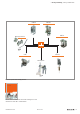
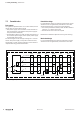
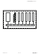
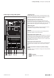
The block diagram shows the typical design of a u-control
station. The power supply concept here makes sure that,
starting with a certain capacity utilisation, power refresh is
implemented using power-feed modules.
+24 V DC
5
3
2
2
+24 V DC
+24 V DC
DI/AI
System bus
U
SYS
U
IN
U
OUT
DI/AIDO/AO PF-O PF-IDO/AO
+24 V DC
u-remote power supply concept
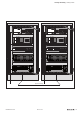
Potential-free design
In a potential-free design, the reference potentials of control
and load circuits are galvanically isolated from each other.
A potential-free design is necessary for the following:
– Use of the power-feed module (in both the PF-I and PF-O
variants), i.e. in all AC load circuits
– DC load circuits that cannot be coupled
Potential-free installation depends on the type of earthing.
Non-isolated design
In a non-isolated design, the reference potentials of control
and load circuits are galvanically connected to each other.