
User Documentation


36 2604080000/03/08.2020Manual u-control
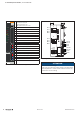
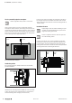
5 Detaildescriptionofcontrollers | UC20-SL2000-EC-CAN
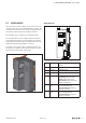
PWR
SF
BF
MT
RUN
L/A X1
L/A X2
Service
X3
SL-EC-CAN
Controller power supply LED
Green: supply voltage >18V
Red: at least one current path < 18 V
3.1 Green: input current path supply voltage >18VDC
3.2 Red: input current path supply voltage <18VDC
3.4 Red: Internal fuse defective
4.1 Green: Output current path supply voltage >18VDC
4.2 Red: Output current path supply voltage <18VDC
4.4 Red: Internal fuse defective
LED indicators UC20-SL2000-EC-CANforerrormessagesseeChapter12
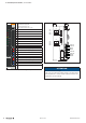
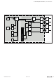
TD+ 1
TD– 2
RD+ 3
RD– 6
GND
CAN L
CAN H
TD+ 1
TD– 2
RD+ 3
RD– 6
X1
X2
X4
24VDC OUT
24VDC OUT
GND OUT
GND OUT
24VDC IN
24VDC IN
GND IN
GND IN
GND
CAN L
CAN H
Connection diagram UC20-SL2000-EC-CAN
ATTENTION
Risk of material damage!
In the case of a maximum power supply > 3 A and a maxi-
mum temperature > +55°C, all four contacts must be con-
nected with 1.5 mm² wiring!