
User Documentation


5 Detaildescriptionofcontrollers | UC20-SL2000-EC-CAN
35Manual u-control2604080000/03/08.2020
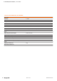
5.4 UC20-SL2000-EC-CAN
Up to 64 active u-remote modules can be connected via
the u-remote system bus to the UC20-SL2000-EC-CAN
controller. The controller has two Ethernet connections for
integration into the existing network architecture or HMI con-
nections.
The controller has a CAN interface. For information regarding
the CAN-based communication protocols, which are support-
ed by the controller, please refer to the documentation for
the u-create studio software.
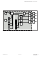
The controller can be congured as a EtherCAT master.
The u-control station can be congured and parametrised
and controlling applications can be programmed using the
engineering tool u-create studio (according to IEC61131-3,
additional programming languages: C and C++)
The station’s main power supply is integrated into the con-
troller. Power is supplied via two 4-pole connectors, separat-
ed into the input and output current paths.
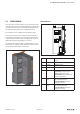
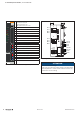
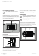
Controller UC20-SL2000-EC-CAN (Order No. 2674620000)
Status indicators
PWR
SF
BF
MT
SL-EC-CAN
1
2
3
4
1
2
3
4
RUN
L/A X1
L/A X2
3
4
X1
X2
GND
CAN L
CAN H
X4
GND
CAN L
CAN H
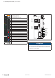
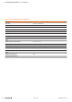
LED status indicators UC20-SL2000-EC-CANforerrormessagesseeChapter12
PWR Power LED green: supply voltage present, rmware is
running
SF System failure red: system bus failure
BF Bus failure red: eld bus failure
MT Maintenance yellow: communication error with module
RUN Controller status green: application running
greenashing: application stopped
yellow: operating system running
yellowashing: system update running
red: serious system failure
L/A X1 Connection/
activity
green: connection of controller connection 1
with an additional eld device
green/yellowashing: data being ex-
changed on connection1
L/A X2 Connection/
activity
green: connection of controller connection 2
with an additional eld device
green/yellowashing: data being ex-
changed on connection2