
User Documentation


3 Systemoverview | Connectable u-remote I/O modules
13Manual u-control2604080000/03/08.2020
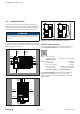
3.3 Connectable u-remote I/O modules
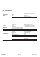
The release notes concerning the controllers
describe which u-remote modules at which rm-
ware version are supported. The release notes
are available to download from the Weidmüller
website.
▶ Please regard the information in the release notes.
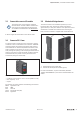
3.4 ConnectorPG1.5mm
A connector frame can take up to four connectors, and four
conductors can be connected to each connector. “PUSH IN”
technology allows for ne-wired conductors with crimped
wire-end ferrules or ultrasonically welded conductors, each
with a maximum cross-section of 1.5mm², to be inserted
easily through the opening in the clamping terminal without
having to use tools. To insert ne-wired conductors without
wire-end ferrules, the pusher must be pressed in with a
screwdriver (wiring see section 6.3).
ConnectorPG1.5mmwithfourconductorconnections
– conductor cross-section 0.14 to 1.5 mm² (AWG 16 – 26)
– max. ampacity: 10A
– 4-pole
The pushers are colour-coded for the following connections:
White Signal DC or AC
Blue GND
Red 24VDC
Green Functional earth (FE)
Black SignalAC
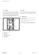
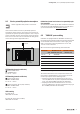
3.5 Mechanicalxingelements
The station is xed in the installation position by an end
bracket at either side. The last I/O module is protected
against dust by a cover plate. Into this cover plate the second
end bracket is inserted and screwed to the mounting rail.
Every u-control controller is supplied with a termination kit.
1 2
u-control station fixing elements
1 End bracket (left end, on the controller side)
2 Termination kit with end plate and end bracket (right end)
For vertical installation, a special end bracket (Order No.
1805610000 MEW 35/1) must also be installed below the
station.