
User Documentation
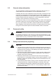
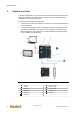
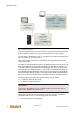
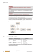
Table Of Contents
- Table of contents
- 1 Introduction
- 2 Safety instructions
- 3 System overview
- 4 Operating behavior
- 5 Software installation
- 6 Configuration
- 7 Program development
- 8 Licensing
- 9 Device Administration (DevAdmin)
- 10 Software units
- 11 OPC UA Server
- 12 Node-RED
- 13 LongtermDiagnosticMonitor
- 14 Data recorder
- 15 Diagnostics
- 16 Maintenance
- 17 Technical data
- 18 Directives and standards
- 19 Appendix: Tutorial - creating an IEC project
- 20 Appendix: Addressing in the Ethernet (basics)
- 21 Appendix: Tutorial FoE
- 22 Appendix: Tutorial - call C function from IEC
- Index
System overview
System manual
2696790000/02/04.2020
18
Information
To change the IP address of a panel the device must be connected to a
network.
The IP addresses of the I/O modules are set in u-create studio EoE settings
(see online help).
Information
A maximum of 3 handheld terminals can be used simultaneously.
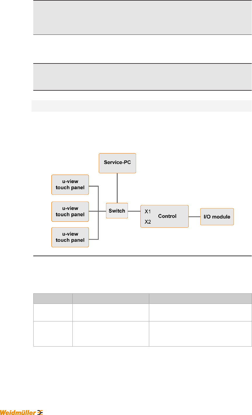
Connection service PC - system components
For a service PC to be able to communicate with additional components, it
must also be located in the machine network. For that, the service PC is ei-
ther connected via a switch or directly to the X1 port of the control and must
get an IP address by the user that is compatible with the network.
Fig.3-3: Service PC in the machine network
3.4 u-control - CPU modules
Designation Performance data Interfaces
UC20-SL2000-
EC
Dual Core A9, 512 MB RAM, 8
GB EMMC
● u-remote bus
● EtherCAT Master
UC20-SL2000-
EC-CAN
Dual Core A9, 512 MB RAM, 8
GB EMMC
● u-remote bus
● EtherCAT Master
● CANopen interface
For further information, please refer to the u-control manual or the product
catalog (Automation section).