
User Documentation
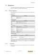


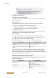
Table Of Contents
- Table of contents
- 1 Introduction
- 2 Safety instructions
- 3 System overview
- 4 Operating behavior
- 5 Software installation
- 6 Configuration
- 7 Program development
- 8 Licensing
- 9 Device Administration (DevAdmin)
- 10 Software units
- 11 OPC UA Server
- 12 Node-RED
- 13 LongtermDiagnosticMonitor
- 14 Data recorder
- 15 Diagnostics
- 16 Maintenance
- 17 Technical data
- 18 Directives and standards
- 19 Appendix: Tutorial - creating an IEC project
- 20 Appendix: Addressing in the Ethernet (basics)
- 21 Appendix: Tutorial FoE
- 22 Appendix: Tutorial - call C function from IEC
- Index

Diagnostics
System manual
2696790000/02/04.2020
97
15 Diagnostics
This chapter describes the diagnostic options of u-create. Depending on the
delivery, not all diagnostics options may be available.
15.1 Control diagnosis
Errors during operation or operating states are indicated via the LEDs on the
CPU module.
PWR (Power)
Indication Meaning
Dark No voltage supply
Green Device running
SF (System Fault)
Indication Meaning
Dark No voltage supply or no error
Red Severe system error (e.g. Fatal Error)
RUN
Indication Meaning
Dark No voltage supply
Green Application is processed or setup finished
Flashing green Application is stopped
Yellow Ready for operation
Flashing yellow Setup is executed
Flashing red Setup failed
Link/Activity LED
Indication Meaning
Dark No connections
Flashing green/yellow Data is transferred
Green EtherCAT connection established (100 MBit/s, Full Duplex)
Via the Service App "DevAdmin" information of the control can be read and a
state report as well as a crash report can be triggered. (see Device Adminis-
tration (DevAdmin)).
15.1.1 Error codes
Depending on the version of the CPU module, different error messages can
be displayed.