
User Documentation
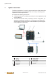
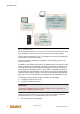


Table Of Contents
- Table of contents
- 1 Introduction
- 2 Safety instructions
- 3 System overview
- 4 Operating behavior
- 5 Software installation
- 6 Configuration
- 7 Program development
- 8 Licensing
- 9 Device Administration (DevAdmin)
- 10 Software units
- 11 OPC UA Server
- 12 Node-RED
- 13 LongtermDiagnosticMonitor
- 14 Data recorder
- 15 Diagnostics
- 16 Maintenance
- 17 Technical data
- 18 Directives and standards
- 19 Appendix: Tutorial - creating an IEC project
- 20 Appendix: Addressing in the Ethernet (basics)
- 21 Appendix: Tutorial FoE
- 22 Appendix: Tutorial - call C function from IEC
- Index

System overview
System manual
2696790000/02/04.2020
19
3.5 Buses
The sections below list the buses supported by the u-create system and de-
scribe them in more detail.
The following master fieldbus interfaces are available depending on the con-
trol version:
● EtherCAT
● CAN
● Modbus TCP/IP
The following slave fieldbus interfaces are available depending on the con-
trol version:
● Modbus TCP/IP
3.5.1 EtherCAT
EtherCAT interfaces can be used for the connection of slave devices (e.g.
drives, I/O modules).
Information
The interface X2 can only be used as EtherCAT interface. A use as Ether-
net is not possible.
3.5.2 CAN
When using the CAN interface, make sure to use UC20-SL2000-EC-CAN
with CAN controller.
3.5.3 Modbus TCP/IP
Modbus is an open communication protocol for data exchange between a
master, which requests or writes data, and slaves, which provide or receive
data.
The Modbus protocol is specified for serial connections (Modbus RTU) and
for Ethernet (Modbus TCP). Typical applications are transmission of values
for non time-critical tasks. The data is provided in single register (16 bit val-
ues) or coils (discrete 1 bit values) via a Modbus table defined by the slave
manufacturer.
Configuration
To communicate with a Modbus server on the control, configuration entries
must be set via u-create studio. For detailed information see u-create studio
online help.