
User Documentation
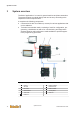
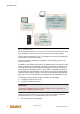

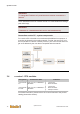

Table Of Contents
- Table of contents
- 1 Introduction
- 2 Safety instructions
- 3 System overview
- 4 Operating behavior
- 5 Software installation
- 6 Configuration
- 7 Program development
- 8 Licensing
- 9 Device Administration (DevAdmin)
- 10 Software units
- 11 OPC UA Server
- 12 Node-RED
- 13 LongtermDiagnosticMonitor
- 14 Data recorder
- 15 Diagnostics
- 16 Maintenance
- 17 Technical data
- 18 Directives and standards
- 19 Appendix: Tutorial - creating an IEC project
- 20 Appendix: Addressing in the Ethernet (basics)
- 21 Appendix: Tutorial FoE
- 22 Appendix: Tutorial - call C function from IEC
- Index

System overview
System manual
2696790000/02/04.2020
15
Information
The system components shown in this manual are example graphics. The
devices used by you may differ in their appearance. Please observe the
supplied operation manuals of the devices.
3.1 Hardware architecture
Devices are connected according to their signal type, e.g. via analog or digi-
tal input or output modules, interface modules, etc.
CPU modules and I/O modules must be integrated into a control cabinet.
Their enclosure only provides mechanical protection; the EMC shielding
happens inside the device. For greater distances between the transducers a
decentralized groups of I/O module clusters can be used. These can be con-
nected with the CPU module via bus link modules.
The operating and display devices can be arranged at a suitable location
somewhere on the machine/plant.
During the start of the system, the runtime system compares the current
hardware configuration (actual configuration) with the hardware configuration
(set configuration saved in the u-create studio project. Deviations in configu-
ration or faulty modules can be identified via the inquiry of the module status
in the IEC application. The response is set here via the program (e.g. error
output on the visualization, restricted function in the optional I/O modules,
etc.)
3.2 Software structure
The following graphic shows the structure of the software on the u-create
system.