u-create Studio
Document No.: Filename: Pages: 76 Specifications are subject to change due to further technical developments. Details presented may be subject to correction. All rights reserved. Weidmüller Interface GmbH & Co.
Record of Revision Record of Revision Version Date Change in chapter Description changed by 1.00 06-2014 - Newly Created hasl 1.01 07-2014 - Several updates swb 1.02 08-2014 - Several updates swb 1.03 05-2015 Create safety appliNew chapter cation hasl 11-2018 Long-term diagnostics; Loading addiNew chapter; several updates tional files on the device swb, raud 1.
Table of contents Table of contents 1 Introduction ................................................................................................................ 1.1 Preconditions ................................................................................................... 1.1.1 Required Hardware ........................................................................... 1.1.2 Required Software ............................................................................. 1.2 Intend use ..........
Table of contents 6.4 Loading additional files to device ..................................................................... 27 7 Open project from device .......................................................................................... 29 8 Export and import projects ....................................................................................... 8.1 Create project template....................................................................................
Table of contents Index ............................................................................................................................
Table of contents 8
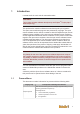
Introduction 1 Introduction u-create studio is a tool suite for automation tasks. Information This product includes software developed by the EclipseTM Project (http:// www.eclipse.org). This product also contains software that was developed by third parties. The open source software programs are protected by copyright. The open source software can be used in accordance with the respective open source software license conditions.
Introduction Target group Prerequisite knowledge and abilities Basic technical training (technical college, engineer training or corresponding professional experience). Programmers Knowledge about: ● ● ● Current valid safety regulations, method of operation of a PLC and programming of a safe PLC. Basic technical training (technical college, engineer training or corresponding professional experience).
Introduction information must be integrated in the instruction manual for end users in the specific national language by the mechanical engineer or the system provider. This documentation must be legible and available to the specified persons and must be read and understood by them. 1.3.1 Contents of the document Description of the: ● ● ● ● 1.3.2 Not included in this document ● ● ● ● ● 1.
Safety notes 2 2.1 Safety notes Representation At various points in this manual, you will see notes and precautionary warnings regarding possible hazards. The symbols used have the following meaning: DANGER! indicates an imminently hazardous situation, which will result in death or serious bodily injury if the corresponding precautions are not taken. WARNING! indicates a potentially hazardous situation, which can result in death or serious bodily injury if the corresponding precautions are not taken.
Installing u-create studio 3 Installing u-create studio Please note the system manual and the manual controllers u-control.
User interface 4 User interface This chapter describes the user interface of the u-create studio. 4.1 Operation Standard functions under Windows® such as drag & drop, copy & paste, individual adaptation of the user interface by docking, pinning of windows and menu bars are known by nearly all PC users and can be easily learned by simply trying them out. They are therefore not described in more detail in this document. We refer to the literature provided on the Internet about the listed topics.
User interface 4.2.1 5 ... Variables browser 6 ... Watch Monitor 7 ... Message window 8 ... Action Log Menus and toolbar The useable commands in u-create studio can be activated from the menu bar, the tool bar or from context menus. Only u-create studio-specific commands are described here. For the benefit of a better overview, the explanation of generally known standard commands will be dispensed with. The following tables show an overview about the u-create studio-specific menus.
User interface 4.2.2 Project tree The project tree shows the current project and the devices contained in the project. Double-clicking on an entry opens the associated work area or the associated editor. Fig. 4-2: Project tree The elements in the project tree are depicted in a logical sequence (e.g. addon capable modules under bus system, bus system under CPU, etc.) and can only be inserted in the specified sequence.
User interface 4.2.7 Action Log In the "Action Log" are the actions from the user and the implicit actions from the system logged. This can be used to get an overview of the actions.
Create project 5 Create project In addition to the required steps for creating a project, this chapter also describes additional, important functions for the project administration (exporting/ importing project, managing device description files). In general, a complete configuration requires the following essential steps: 1) 2) 3) 4) 5) 6) 5.
Create project 5.2 Insert devices In order to create a configuration, the required devices must be inserted into the project tree. Actions for inserting devices The following actions are available for inserting devices: Action Description Add device The new device will be subordinated to the selected device. Insert device The new device will be inserted after the selected device, on the same level.
Create project Information If you delete a device, all subordinate objects are also removed. This action can be undone with Edit - Undo. Update device Devices can be updated to a newer version or to a different type. Similar to Add Device is Update Device in the context menu. Information When changing the type of the device all settings will be lost and the subdevices can be preserved only in certain cases. This also applies to devices with small differences. 5.
Create project Fig. 5-4: I/O Mapping Depending on the type of I/O module, channel-specific features can be activated, deactivated and parameterized separately for each channel using drop-down menus or text input fields. Fig. 5-5: Additional settings or DIs Fig. 5-6: Features checkbox in IO Mapping Some modules have parameters that are not channel-bound, e.g. the 1SSI module. The tab also offers the option to permanently override its endpoints for the runtime (forcing).
Create project 5.5.1 Printing endpoint mapping The mapping of the endpoint can be printed for easier wiring. To do so, the print function must be used via File - Print.
Loading project on control 6 Loading project on control With u-create studio the project can be downloaded to a control. For the online option, you need to establish a connection to the running control first. 6.1 Establishing Connection PC - Control Double-click on the node of the control in the project tree to open the editor with the configuration of the control. There is also an individual "Communication Settings". A connection to the control can be created there. Fig.
Loading project on control 2) Upon completion of the search run you can select the searched control in the tree and activate it in the project via the tool bar with the help of "Set Active". This establishes the connection to the control and the status of the control is already indicated in the project tree. Alternatively, you can also set a found control to active by double-clicking on it.
Loading project on control To exit the error state of the control the context menu of it has to be opened in the project tree and the control process must be stopped via Device manipulation - Stop Controller. Then the application must be deleted with Device manipulation - Delete Application. After successfully deleting the application the control process can be restarted via Device manipulation Start Controller and a new application can be downloaded to the control.
Loading project on control Fig. 6-11: Authentication during Login 3) After the login you will automatically be given the option to execute an OnlineChange. Fig. 6-12: OnlineChange if parts of project are capable After a login and OnlineChange of the application to control is done, information of application (e.g. values of variables) are available in u-create studio. Furthermore different manipulations of application during runtime are possible (e.g. force of variable values in watch monitor). 6.
Loading project on control At Download and Login to Device the whole project will be automatically downloaded to the device and a login will be performed. In this process all builds and generate processes will be executed to get the latest version of all project parts to the device. This option is only available in specific systems. At Selective Download to Device a dialog will show the elements of the project from which the parts for download can be selected. Fig.
Loading project on control of the two optional directories masterdisk or workspace. After a selective download, the files are also located in the masterdisk or workspace directory on the device. Fig.
Open project from device 7 Open project from device A project archive that was downloaded during download can be uploaded and opened with File ► Open Project from Device .... In the following dialog the device from which the archive should be loaded can be selected. Fig. 7-16: Open project from device The desired device can be selected from the result list of a device scan or added directly with "Add Device". After pressing the button "Open" the username and password must be entered.
Export and import projects 8 Export and import projects Parts of the project or the entire project can be exported and reimported into a file. This allows you to reuse already created configurations and exchange these between two projects or backup projects. Export project To export part of a project or an entire project, proceed as follows: 1) In the menu, select Project - Export.... A selection dialog opens. Fig. 8-17: Selection dialog 2) Select the parts to be exported. 3) Confirm your input with OK.
Export and import projects A template consists of the following files: File Description .project Project file copied from an existing project .template XML file with text for template name, .... in different languages. To create a template, proceed as follows: 1) Open or create a project that will be used as a template later. Devices can be added and parameters can be configured here too. 2) Save the project. 3) Close u-create studio. 4) Copy the saved project file .
Managing packages 9 Managing packages Furthermore, it is possible to manage device description files as well as plugins that are available in the u-create studio by installing or uninstalling packages via the Package Manager. A package includes several device description files and library files and offers the advantage that complete system configurations can be installed in one step. Fig. 9-18: Package Manager The package manager can be opened in the menu via Tools - Package Manager.
Create and execute the simulation of a control 10 Create and execute the simulation of a control It is possible to create and execute a simulation of the control using u-create studio. The simulation service must be installed and started. This is usually done automatically by the general setup. In order to be able to simulate a project, the device in the device tree must first be changed to the simulation device.
Create and execute the simulation of a control Name Beschreibung Description An additional information that can help when managing simulations. Optional Packages The optional PLC packages which should be used can be selected in the following dialog. ● ● Location Build settings Managed by simulation service: with this option the created simulation will be stored in a directory on the machine where the service is hosted.
Create and execute the simulation of a control Name Remove 10.3 Beschreibung Deletes a simulation. Execute local simulation To execute a local simulation the .exe file in the simulation directory must be executed. Fig. 10-21: Directory of a local simulation A window will be opened with the informations of the simulation. If the simulation contains a visualisation, it is started automatically.
Create and execute the simulation of a control Fig.
Update software 11 Update software u-create studio provides to execute an update of the software directly via the tool. Therefore a log in on the control must happen. Then the control settings are opened via double-click on the control node in the project tree. Via "Software update" on the area "Info" can be checked if there is new software available. If this is the case this is shown in a dialog and a software update can be executed.
Load firmware on device 12 Load firmware on device There is the possibility to install the firmware on a device (e.g. control) via a removable disk. Thereby, the whole control operating system, the runtime system and the application is stored on the removable disk and can be installed on any number of devices. Therefore the following configuration settings have to be inserted in u-create studio in the menu Tools ► Optionen...
Load firmware on device Name Description Selection of the removable disk or any folder. If no removable disk is selected, a warning will be shown and the content is saved in the selected directory. Destination: If a removable disk is selected, it is checked whether the removable disk is a valid Service Medium. If it is no valid Sevice Medium, a warning is shown and the removable disk can be made valid or bootable via clicking on "Prepare Service Medium (Administrator privileges required)".
Load firmware on device Fig. 12-25: Dialog - Compatibility settings After all settings are made, the software can be stored on the removable disk via "Create" (dialog "Create target"). Therefore, the removable disk is available for the installation of the firmware on the desired devices.
Manage devices 13 Manage devices u-create studio provides the possibility to manage devices on a removable storage device, to change network settings of devices. Furthermore, all settings of the removable storage device can be deleted and the removable storage device can be formatted, so that it can be used as conventional removable storage device again and is not bootable any more. Therefore Tools ► Manage Targets must be selected in the menu bar. The following dialog is opened: Fig.
Manage devices In this area a device can be selected as default device for a restore at devices with a 7 segment display. In addition, in this area all device configurations of the selected USB stick can be deleted and the stick can be formatted newly.
Prepare Service Medium 14 Prepare Service Medium u-create studio offers the option to prepare a removable disk for the backup of a control or to restore the saved backup on a control. To do so, a removable disk with a memory of at least 2 GB is needed, which is plugged into the PC. Use the menu item Tools - Prepare Service Medium to open a dialogue in which you have to select a removable disk. Fig.
Configuration 15 Configuration The following chapters describe the configuration options in the system. 15.1 Configuration of the message system The message system is used to inform the user about processes in the control, which either can no longer guarantee a correct function or signal important status changes in the control process. The message editor is opened in the project tree via Message Editor. 15.1.1 Message Editor Proprietary messages can be created and edited in this editor.
Configuration Unique number for a message. This number must be indicated when calling SetMessage. Since the same message with the same message text but different parameters can be called multiple times in the application program, it must be identified there in a unique manner by an instance number. Message text The message text entered here is attached to the message when it is called by SetMessage.
Configuration Fig. 15-29: Status model for the messages 15.1.2 Export/import message texts Via "CSV Export", the currently displayed messages can be saved in a separate file. Via "Version Code", the file can be given a version ID. Via "CSV Import", already created messages can be imported into the current project. Messages from the device can be imported into the project by using "Import". Hereby only messages of the applikation will be imported. Messages of the base system will not be imported.
Configuration 15.1.3 Translate messages The created, currently displayed messages can be translated into another language. To do so, a proprietary program (Translator) is pulled up with "Translate". For more information about the operation: See online help of the translator program. 15.2 Configuration of modbus server To communicate with the modbus server on the control the following configuration entries must be set via "Expert Entries" directly on the node control: [ModBus] enableRTU = 0 [ModBus.
Configuration 15.3 Configuration of EtherCAT devices In principle, EtherCAT devices can be configured as "EtherCAT Master" or "EtherCAT Slave". Several EtherCAT Slave devices can be connected to a EtherCAT Master (e.g. the control functions as master and can be connected with slaves). 15.3.1 Configuring EtherCAT Master Open the configuration window by double-clicking on the EtherCAT node.
Configuration Element Meaning Max. start offset Maximum of the send times of the "normal"-frame relative to the systick Max. start time DMA statistics: the maximum time before the first data is available (graphical representation available by clicking the button) Max.
Configuration EtherCAT master and EtherCAT controller have a common area in the RAM for data transfer. There the EtherCAT master saves the data to send and gets the data to receive. The EtherCAT controller has (as usual for network controller) direct access to the common RAM area (Direct Memory Access) and transfers the data immediately to the EtherCAT bus (RAM transfer). So a data stream between RAM and EtherCAT bus is created.
Configuration 15.3.2.1 Telegram losses If a telegram loss is detected on the EtherCAT bus, a message is reported. Depending on the value of the configuration parameter frameLossTolerance, this message is reported either as an error or as a warning. The message is reported as a warning if the number of telegram losses in the last ten transmissions has not exceeded the telegram loss tolerance configurable by the configuration parameter frameLossTolerance.
Configuration WARNING Ackn (6353/73), ECAT: Timing violation occurred (DMA) WARNING Ackn (6353/73) ECAT: Timing violation occurred (SW normal) WARNING Ackn (6353/73) ECAT: Timing violation occurred (SW early) If timing violations occur repeatedly within ten EtherCAT bus cycles, the message is sent as an error and the error status of the end points affected by the process data is set invalid.
Configuration Information If the value is greater than the configured bus cycle time, the cycle time must be adapted correspondingly. 15.3.2.3 Consequence An increment of these times has the following consequences: ● ● ● 15.3.3 Reduction of the amount of data which can be transmitted on the bus, because the time available for transmission is reduced. Reduction of the time between "reading inputs" and "writing outputs" at a configured "fast control". Possibly necessary higher bus cycle time.
Configuration Tab "Basic Configuration" Like for all configuration windows, the structure for EtherCAT slave devices is split into three parts "General", "Info", and "Advanced". For normal operation parameter of part "Advanced" need not to be changed. Furthermore, the area "General" is also split into the areas "Device Identification", "Distributed Clock" and "Sync". Fig. 15-31: Part "General" General Element Meaning ● Timing mode ● ● ● Cycle Time: Insert a cycle time in μs.
Configuration Fig. 15-32: Part "Device identification" Device identification Element Activate Device Identification Meaning This activates the function and releases the necessary parameters. Assign identification ID to slave so that the EtherCAT master knows the order of the added devices (will not be written on slave). The following options are available for selection: Identification Mode ● ● ● Configured Station Alias: To identify the device the configured Stations ID is used.
Configuration Information Some EtherCAT slave devices (without EEPROM) do not support to save the Station Alias. Fig. 15-33: Part "Distributed Clock" Distributed Clock Element Meaning Activate DC With this you can set whether Distributed Clock is to be used. Use Automatic DC When using this option, the "Sync 1" is automatically calculated by the system. Therefore, in this case the settings for "Sync 1" also deactivated in the "Sync" area.
Configuration Element Meaning Cycle Time Cycle time in µs or multiple of slave cycle time, depending on the configured Sync cycle unit. Time Delay Indicates the time between the Sync impulse of control and the Sync 0/1 point in time on the device. Tab "I/O Mapping" In this tab the endpoints can be mapped to a device (see chap. "Mapping endpoints").
Configuration Element Meaning Firmware Version Firmware Version Hardware Revision Hardware Revision First operation date Delivery time Operation time Operating hour count ECAT state State of the slave Active ECAT transition Active ECAT transition AL status code AL status code for transition AL status code description AL status code description In the list "Device messages" are the messages of the device since the last start up listed.
Configuration Designation 15.4 Meaning Subnet mask the corresponding subnet mask Default Gateway the standard gateway DNS Server Address of a DNS (Domain Name System) server DNS Name Name of a DNS (Domain Name System) server Configuration of CAN devices In principle, CAN devices can be configured as "CAN Master" or "CAN Slave". Several CAN Slave devices can be connected to a CAN Master (e.g. the control functions as master and can be connected with slaves). 15.4.
Configuration In the part "Advanced" you can find further parameters of the CAN bus in a tree structure. For normal operation this parameters need not to be changed. Tab "Status" Various analysis parameters are shown here, which provide information about the CAN bus of a running control. Element 15.4.
Configuration Fig. 15-37: Add CAN Master 2) Select category ► "CANopenManager", device ► " CANopenMaster" in the open dialog and confirm with "Add device". The CAN Master node is assigned to the CAN interface of the device. Double-clicking the CAN node opens the configuration dialog. Tab "CANopen Master" In this tab the general master configuration can be carried out. Fig. 15-38: CAN Master configuration dialog Element Node address Meaning Selecting a unique node address of the pre-defined node area.
Configuration To do so, proceed as follows: 1) Open the context menu of the CAN Master in the project tree and select Add Device. 2) Select a CAN Slave device in the open dialog and confirm with Add Device. A CAN Slave device has been inserted. Double-clicking the CAN Slave device in the project tree opens the configuration dialog. The configurationpossibilities in this window depends on the device inserted.
Configuration Fig. 15-39: Part "General" Element Meaning Timing Mode Cycle time of the Slaves. Only for selected Slaves a cycle time differently to the Master can be configured (e.g. BL210). Expert settings Activate expert settings for additional configuration. CAN Slave devices can be configured so that they do not always have to be physically present in order to be able to perform tests.
Configuration Fig. 15-40: Configuration dialog "Endpoint configuration" In this tab it is possible to separate the memory range of a PDO to several inputs and outputs. So the data of the PDO can be processed in different ways and can be used at the I/O mapping separately. In the respective tab all configured PDOs with the inputs and outputs are listed. For each inputs or output an unique name as well as the data type can be configured.
Configuration Fig. 15-41: Configuration dialog "PDO configuration" In this dialog it is possible to configure the parameters Timeout and Message Loss Tolerance for each PDO that is transmitted from the slave to the master. The parameter Timeout defines the allowed time from the start of the device until the master receives the first PDO. If this time is exceeded an error is triggered. The default value is tem times the cycle time of the device.
Configuration Information Activating the hearbeat function is only possible, if node guarding is not activated. Fig. 15-43: Part "Heartbeat" Element Meaning Activate Heartbeat Activating heartbeat function Heartbeat cycle time Interval between consecutive heartbeats (in s) Fig. 15-44: Configuration dialog hearbeat monitoring Element Meaning Enable Activates the consuming of the node address. Node ID of Producer Unique identification of the heartbeat producer on the bus.
Configuration Element Meaning Activate node guarding Activating cyclic node guarding of the slave. Is only possible, if heartbeat is not activated. Node guarding time Time, with which the node guarding of this device should be executed. Must be an integer multiple of the CAN- and PDO-cycle time of the device. Life time factor If the factor is unequal 0, the slaves checks the master for failures. Tab "I/O Mapping" In this tab the endpoints can be mapped to a device (see chap. "Mapping endpoints").
Configuration The configured SDO will only be transmitted, if "Download" is selected. If "Abort if Error" is selected, the initialization of the slave will be aborted in case of a defective SDO. Via "Add" new SDOs can be created and the manually created SDOs can be deleted via "Remove". Manually created objects can be sorted with "Up" and "Down" to change the transmission sequence.
Configuration 15.4.3.2 Configuring control as CAN Slave To configure a control as CAN Slave (Adding the function CANopen Local device), proceed as follows: 1) Open the context menu of the CAN interface and select ► Add Device 2) Select category ► "Local Device / ► CANopen Local Device"in the dialog and confirm with "Add device". Fig. 15-48: Insert CAN Slave Information The device itself is called "local device", if it serves as master and is also configured as slave.
Configuration General Fig. 15-49: Part "General" Element Meaning If the device is used as slave it can be configured so that the master not always have to be physically present in order to be able to perform tests. The following selection options are available for that: Availability ● ● Mandatory: The availability of the master is mandatory: Optional: In this setting, the operation with and without existing master device possible, while the device is actually controlled if it is present.
Configuration To use the device as CAN Slave, all parameters have to be completely configured. Via pressing "Generate file ..." a EDS-description file is generated, which can be saved separately. Information The device description file must be installed manuallly so that the device is available for use. Tab "I/O Mapping" In this tab the endpoints can be mapped to a device (see chap. "Mapping endpoints").
Configuration Element Meaning Name Insert unique name. Count Select required length of the in-/output, length is limited. Data Type Select data type. Force new PDO Activate to use a separate PDO for the in-/output. It is shown how many inputs (Tx) or outputs (Rx) are already configured. Fig. 15-53: Number of used PDOs Created inputs and outputs parameters can be deleted via "Remove". Add SDO parameters It is possible to add SDO parameters in the tab "Object Editor".
Diagnosis 16 Diagnosis In this chapter, the diagnostic options with u-create studio are described. A diagnosis is only possible after logging into the control, since otherwise no parameters/values are read from the control. In the project tree the status of the devices and busses is indicated with a corresponding icon. Icon Meaning Device or entire device node has no errors. Device is optional and not connected. An error has occurred in the device affected.
Diagnosis Fig. 16-55: Message monitor "Alarm" messages can be acknowledged via the context menu. Multiple selections are possible. 16.2 Variable Browser The variable browser displays the system variables of the IEC application. Variables are only displayed if you are connected with the control and if you are logged in. The variables are displayed in the variables browser, including their directory structure.
Diagnosis Name Set all default values 16.4 Description Write values that were entered in the column "Predefined Value" on the variable in the control Trace In the Tracemonitor the Trace of the control will be shown in an easy readable way. It can be opened by double click on Diagnostics - Trace. Fig. 16-56: Trace The trace can either be watched live from the control or a previously saved can be opened by clicking "Open". For the live viewing is a login to the control required.
Index Index O U Operation................................................. 14 User interface Operation ............................................