
User Documentation

Weidmüller t
Weidmüller Interface GmbH & Co. KG
Klingenbergstrasse 16
32758 Detmold
Germany
www.weidmueller.com
R.T.No. 1477400000/02/08.14
en
Operating Instructions
TERMSERIES Adaptor
TIA F10 1463520000
TIA SUBD 1463530000
TIAL F10 1463540000
TIAL F20 1463550000
1
2
3
4
5
1
3
4
2
A
D
B
C
E
14
A1 +
A2 -
1122770000
TRS 24VDC 1CO
24V
24V
1114 12
A2
NO
11
12
COM
NC
14 11
A1 A2
TOSTRS
A1
14
A1 +
A2 -
1122770000
TRS 24VDC 1CO
24V
24V
1114 12
A2
NO
11
12
COM
NC
14 11 A1
A2
TOSTRS
A1
Figure 2a
Figure 3a
24 V DC
–
6810
9 7 53
42
1
+
+
–
Figure 5a
24 V DC
–
161820
19 17 15 13
14 12
11
+
10
9
8
7
6
5
4
3
2
1
+
–
Figure 5b
24 V DC
–
678
15
14
13 12
54
11
+
10 9
3
21
+
–
Figure 5c
Figure 2b
Figure 3b
Safety instructions
DANGER
For safe installation and safe operation of the device,
heed the following:
• The device must only be installed by qualied spe-
cialists who are familiar with national and internation-
al laws, provisions and standards in the relevant region
of application.
WARNING
• All applicable technical requirements and operating in-
structions must be taken into account before installa-
tion, commissioning and maintenance.
• Do not plug and unplug under load!
• The potential of the auxiliary voltage must correspond
to the potential of the I/O component assembly.
• Ensure the correct polarity of the potentials. Avoid in-
correct polarity!
• Heed the technical data!
• The adaptor is installed in the cross-connection chan-
nels of the TERMSERIES products and not on the con-
nection terminals.
NOTICE
• The TERMSERIES adaptor is suitable for positive and
negative switching logic in 24 V DC circuits.
• The potential switch must be set prior to installation.
cULus-approval
NOTICE
• Use copper conductors only.
• The device shall only be used in an environment with
pollution degree 2.
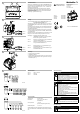
Potential change-over switch
The potential change-over switch (C) is located between contact
rows (A) and (B) of the TERMSERIES adaptor. It is used to switch
the potential of the lower contact row (B) to the “+” or “-” potential of
the auxiliary voltage.
The auxiliary voltage potential is either fed in via the plug-in
connectors (D) (F10, F20, Sub-D) or via the separate push-in
connections (E).
When delivered, the potential change-over switch is in the
“-” position (positive-switching logic).
Installation
Depending on the wiring logic, the TERMSERIES adaptor is
plugged into the
>>>> cross-connection channels <<<<
of the input (A1/A2) (Figure 2) or the output (11/14) (Figure 3) of
the TERMSERIES. The adaptor must be heard and felt to snap into
place.
Then, the ribbon cable or Sub-D plug must be plugged in as well as
the auxiliary voltage connected to the separate push-in connections
if necessary.
In order to loop the auxiliary voltage, the push-in connectors
are duplicated (except TIA SUBD). The loop can conduct 10 A
maximum.
The distance between the cable conduits must be at least 140 mm.
We recommend 160 mm for easier installation.
Installation tip: First plug the adapters into the TERMSERIES
products before snapping the entire block onto the
mounting rail!
Figure 2a: Installation for 24 V DC input (A1/A2), positive-
switching logic, potential change-over switch to “-”.
Figure 2b: Installation for 24 V UC input (A1/A2), negative-
switching logic, potential change-over switch to “+”.
Figure 3a: Installation for output (11/14), positive-switching
logic, potential change-over switch to “+”.
Figure 3b: Installation for output (11/14), negative-switching
logic, potential change-over switch to “-”.
De-installation
• Power down the system!
• Remove cabling
• Use a screwdriver (e.g. SD 0.6x3.5x100, order number
9008330000) to lever out the adaptors via the guides provided
(Figure 4)
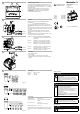
Block diagram
Figure 5a TIA F10, TIAL F10
Figure 5b TIAL F20
Figure 5c TIA SUBD
Technical data
Auxiliary voltage: 24 V DC ±20 %
Continuous current: max. 1 A (per conductor or as total
current)
Wire cross-section: < 1.5 mm²
(push-in auxiliary connection)
Operating temperature: -40...+60 °C
Further details on the push-in auxiliary voltage connection can be
found under part number 1875050000 at http://catalog.weidmueller.
com.
IND. CONT. EQ
IVD3