
User Documentation

1
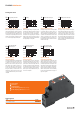
Time setting
2
Timescale
3
Timing function
4
Status display (green): Supply voltage
5
Status display (yellow): Relays closed
1
2
3
4
5
Timing functions
Type Order-No.
TFIS 12-240VUC 1CO M7C 2697250000
Ordering data
TFI-SERIES - Multifunction
Clock generator pause rst (Bp)
When the supply voltage U is applied, the set
interval t begins. After the interval t has expired,
the output relay R switches into on-position and
the set interval t begins again. After the interval
t has expired, the output relay switches into off-
position. The output relay is triggered at a ratio
of 1:1 until the supply voltage is interrupted.
On-delay (E)
When the supply voltage U is applied, the set
interval t begins. After the interval t has expired
the output relay R switches into on-position.
This status remains until the supply voltage is
interrupted. If the supply voltage is interrupted
before the expiry of the set interval, the interval
t already expired is erased and is restarted when
the supply voltage is next applied.
On-delay with control input (Es)
The supply voltage U must be constantly applied
to the device. When the control contact S is
closed, the set interval t begins. After the inter-
val t has expired the output relay R switches into
on-position. This status remains until the control
contact is opened again. If the control contact
is opened before the interval t has expired , the
interval already expired is erased and is restar-
ted with the next cycle.
Off-delay with control input (R)
The supply voltage U must be constantly ap-
plied to the device. When the control contact S
is closed, the output relay R switches into on-
position. If the control contact is opened, the set
interval t begins. After the interval t has expired
the output relay switches into off-position. If the
control contact is closed again before the set in-
terval has expired, the interval already expired is
erased and is restarted.
Bp
A1 / A2
Clock generator pause first
B1 / A2
15 / 18
LED U/T
TTTT
A1 / A2
B1 / A2
15 / 18
LED U/T
T
E
On-delay
<T
A1 / A2
B1 / A2
15 / 18
LED U/T
Es
On-delay with control input
T
<T
A1 / A2
B1 / A2
15 / 18
LED U/T
T<
T
R
Off-delay with control input
Single shot falling edge
with control input (Wa)
The supply voltage U must be constantly applied
to the device. Closing the control contact S has
no inuence on the condition of the output R.
When the control contact is opened, the output
relay switches into on-position and the set in-
terval t begins. After the set interval has expi-
red, the ouput relay switches into off-position.
During the interval, the control contact can be
operated any number of times. A further cycle
can only be started when the cycle run has been
completed.
Single shot rising edge
with control input (Ws)
The supply voltage U must be constantly ap-
plied to the device. When the control contact S
is closed, the output relay R switches into on-
position and the set interval t begins. After the
interval t has expired the output relay switches
into off-position. During the interval, the control
contact can be operated any number of times. A
further cycle can only be started when the cycle
run has been completed.
Single shot rising edge
supply voltage controlled (Wu)
hen the supply voltage U is applied, the output
relay R switches into on-position and the set
interval t begins. After the interval t has expired
the output relay switches into off-position. This
status remains until the supply voltage is inter-
rupted. If the supply voltage is interrupted be-
fore the interval t has expired, the output relay
switches into off-position. The interval already
is erased and is restarted when the supply vol-
tage is next applied.
A1 / A2
B1 / A2
15 / 18
LED U/T
TT
Wa
Single shot falling edge
with control input
A1 / A2
B1 / A2
15 / 18
LED U/T
T
Ws
Single shot rising edge
with control input
T
A1 / A2
B1 / A2
15 / 18
LED U/T
T<T
Wu
Single shot rising edge
supply voltage controlled
A1 / A2
B1 / A2
15 / 18
LED U/T
T<
T
Wu
Single shot rising edge
supply voltage controlled