
User Documentation


Installation
5662300000/01/08.10
25
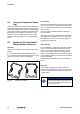
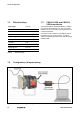
6.3 Marking
Two markers are located below the top sets of ter-
minals for costumer identification.
A
Figure 6 Module marker
A Markers
Article number:
1609880000 WS 15/5 MC NEUTRAL PU 480
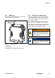
6.4 Electrical Connections
Input, output and power supply wiring is made via
numbered, pluggable connectors, which may be
screw clamp or tension clamp type, depending on
the item article number.
The connectors are coded to prevent the power
supply connector being fitted in the wrong position.
Test terminals are included to permit input and out-
put currents to be monitored without disconnection
of cables (see connection diagram below).
WARNING!
WAVE TTA and PC have to be fully de-
energized, before the programming in-
terfaces CBX100 USB or CBX200 USB
will be connected.
NOTICE
Ensure that the connectors are inserted
into the correct position (see connec-
tion diagram).