
User Documentation


15
Functionaldiagrams
1438130000/02/07-2018
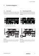
7.1 Autostart
Reset input S33 is connected to S35. Supply voltage
is applied to A1/A2. The unit starts with a rising edge
of the signal at safety inputs S11/S12 and S12/S22.
A1/A2
S33/S35
S11/S12
S21/S22
K2
K1
T
R
T
A
T
A
T
E
= 30 ms (switch-on time K1 and K2)
T
A
= 15 ms (switch-off time K1 and K2)
T
R
= typ. 50 ms (reaction time with bridge over C1/C2)
T
R
= typ. 20 ms (reaction time without bridge over C1/C2)
T
E
T
E
T
A
T
A
24 V DC
0 V
optional
bridge
autostart
bridge
S33/S35
Attention
Make absolutely certain that there is no unexpected
start-up after there has been an interruption in the
supply voltage.
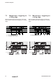
7.2 StartthroughA1/A2
Reset input S33 is connected to S35. Safety inputs
S11/S12 and S12/S22 are bridged. After application
of supply voltage at A1/A2, the enable current paths
are closed.
A1/A2
S33/S35
S11/S12
S21/S22
K2
K1
T
E
T
E
T
A
T
E
= 55 ms (switch-on time K1 and K2 with bridge over C1/C2)
T
A
= 55 ms (switch-off time K1 and K2 with bridge over C1/C2)
T
A
T
E
T
A
24 V DC
0 V
optional
bridge
autostart
bridge
S33/S35
DO
Safety
PLC
Attention
Make absolutely certain that there is no unexpected
start-up after there has been an interruption in the
supply voltage.
7 Functional diagrams