SIL Safety Manual Manual Monitoring Safety Relay SCS 24VDC P2SIL3ES
Foreword Revision History Version Date Change 0.0 03/2013 First Edition 1.0 02/2018 Page 6, TÜV Logo updated Page 19, deleted 2.0 07/2018 Page 13, table 5.1.3 corrected Contact Address Weidmüller Interface GmbH & Co. KG Klingenbergstraße 16 32758 Detmold Germany Phone +49 (0) 5231 14-0 Fax +49 (0) 5231 14-292083 Internet www.weidmueller.
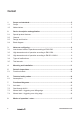
Content 1 1.1 Scope and standards............................................................................................. 5 Scope........................................................................................................................ 5 1.2 Abbreviations............................................................................................................ 5 2 2.1 Device description and application......................................................................
Scope and standards 1 Scope and standards 1.1 Scope 1.2 This safety manual applies to SIL3 relays from Weidmüller‘s SAFESERIES for the following items produced after 11/2012: SCS 24VDC P2SIL3ES 1319280000 SIL3 relays in the SCS 24VDC P2SIL3ES series from Weidmüller Interface GmbH & Co KG Klingenbergstraße 16 32758 Detmold Germany have been certified by TÜV NORD CERT GmbH Certification Body Maschinery Notified Body 0044 Langemarckstr. 20 45141 Essen Germany according to EN 61508 SIL3.
Scope and standards FMEDA (Failure Mode, Effects and Diagnostic Analysis): Systematic way to identify and evaluate the effects of different component failure modes, to determine what could eliminate or reduce the chance of failure, and to document a system in consideration.
Device description and application 2 Device description and application 2.1 Special product features • Stop category 0 according to EN 60204-1 • Application up through control category 4 according to EN ISO 13849-1 • Reset button monitoring • Single- and dual-channel activation • Cross-connection detection • 2 enable current paths, 1 signal current path 2.2 General The safety relay in the SAFESERIES product family is certified according to DIN EN 61508 / SIL3.
Device description and application 2.
Notes on configuring 3 Notes on configuring 3.1 Low demand mode of operation according to EN 61508 The SIL3 relays from the SAFESERIES are used in low demand mode, when their demand frequency is no more than one times per year and no more than double the repeated testing frequency (refer to DIN EN 61508-4, 3.5.12). For the demand rate and the associated PFD parameters at an inspection interval Tproof of 12 years, the values indicated in Table 2 apply. 3.
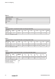
Notes on configuring Table 1 Safety basic data Safety category SIL3 Safety standard DIN EN 61508 Device type A HFT 1 Table 2 Safety parameters “low demand mode” according to EN 61508 Switching cycle PFH SFF 1× per year 2,3 × 10⁻¹² h-1 99,99 % λSD λSU λDD λDU 1,13 × 10⁻¹ FIT 1,6 × 10+1 FIT 1,13 × 10⁻¹ FIT 1,14 × 10⁻³ FIT SIL 3 FIT = 10 h (Failure in time) -9 -1 Table 3 Safety parameters “high demand mode” according to EN 61508 Switching cycle PFH SFF 1× per day 7,87 × 10⁻¹⁰ h-1 99
Mounting and installation 4 Mounting and installation The operating instructions for the SIL3 relay with the order number IS SCS 24VDC P2SIL3ES 1412550000 must be made available. The instructions, constraints and limitations contained in these instructions must be taken into consideration when installing and operating the SIL3 relay. The device may be operated only with an external fuse. If there is a short circuit, you must make sure that the cause of the short circuit has been fixed.
Periodic inspections 5 Periodic inspections The operator must determine the type of tests and the proper time intervals. The time intervals are partly determined by the calculation of each individual safety circuit of the system (the PFD values). 12 The inspections should be carried out so that the flawless operation of the safety functions in conjunction with components can be proven.
Periodic inspections 5.1 Functional check Functional testing is done in three steps according to the following tables. 5.1.
Technical safety values 6 Technical safety values 6.1 Assumptions • The max. allowable ambient temperature is 55 °C. • The environmental conditions correspond to the average industrial environment. 14 • The specifications in the data sheet and the operating instructions should not be exceeded.
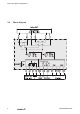
Functional diagrams 7 Functional diagrams 7.1 Auto start 7.2 Reset input S33 is connected to S35. Supply voltage is applied to A1/A2. The unit starts with a rising edge of the signal at safety inputs S11/S12 and S12/S22. Start through A1/A2 Reset input S33 is connected to S35. Safety inputs S11/S12 and S12/S22 are bridged. After application of supply voltage at A1/A2, the enable current paths are closed.
Functional diagrams 7.3 Manual start – triggering on a falling edge When the safety inputs are closed, the reset input S34 is opened using a button (triggering on a falling edge) 7.
Modes of operation / notes 8 Modes of operation / notes • Single- or dual-channel activation -- For single-channel activation, there is no crossconnection detection. • Restart lockout -- There is no restart after the safety inputs have been opened and closed. A restart can be accomplished only by activating the Reset button. For the restart lockout, the reset inputs are to be activated with a button as in the “Manual start” mode of operation.
Modes of operation / notes 18 1438130000/02/07-2018
www.weidmueller.com Weidmüller Interface GmbH & Co. KG Klingenbergstraße 16 32758 Detmold Germany Phone +49 (0) 5231 14-0 Fax +49 (0) 5231 14-292083 Internet www.weidmueller.