
User Documentation


6 2714570000/01/12-2020
Intended use and device description
2.1 Intended use
The safety relay SCS 24VDC P1SIL3ES LL serves
the purpose of safety-related switch-on of process
industry systems (ETS = energised to safe).
The device fulls the safety integrity level 3 (SIL 3)
for low demand mode of operation according to
EN 61508.
2.2 Devicedescription
The input of the safety relay uses a test pulse lter
and three relays connected in parallel. The relay
contacts in the output are connected in parallel (see
block diagram).
The load supply is connected to the L and N con-
nection terminals.
The load is connected to connection terminals 13
and 14.
Connection terminals T1, T2 and T3 must only be
used for checking the relay contacts. In order to do
this, the device must be released and the test cur-
rent must be limited to max. 500 mA.
The device has a diagnostic function. The diagnos-
tic function detects the following faults in the load
circuit:
– Line break
– Short circuit
– Fault in load supply
The error is output at the diagnostic output (con-
nection terminals D21, D22) and at the alarm output
(connection terminals M13, M14) and is indicated
by the “ERR” status LED. The diagnostic output is
a mechanical switching contact (NC contact). The
alarm output is a high-active logic output.
2 Intended use and device description
There are three status LEDs “RLY”, “DIAG” and
“ERR” on the front of the device.
The “RLY” status LED lights up yellow when the in-
put circuit (connection terminals A1 and A2) of the
device is actuated.
The status LED “RLY” does not indicate the
electrical switching state at the device output.
The status change at the device output is
executed with a certain delay after the status
LED indication has changed.
Thediagnosticfunctionofthedeviceis
notasafetyfunction!
The “DIAG” status LED lights up green when the
supply voltage (connection terminals 24V and 0V)
is applied and the input circuit (connection terminals
A1 and A2) of the device is not actuated.
The “ERR” status LED ashes red if the device de-
tects a fault and the input circuit (connection termi-
nals A1 and A2) of the device is not actuated. The
switching contact at the diagnostic output opens.
The alarm output changes from low level to high
level.
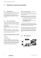
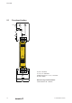
2.3 Blockdiagram
L
DIAG RLY ERR
D21M13M14 D22
A
1
A
2 Logic
Alarm
+24V
N
14
13
T1
T2
T3
24V0V
Diagnostic
Supply
0V