
User Documentation


112714570000/01/12-2020
Proof test
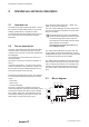
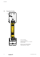
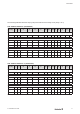
The following table describes the step-by-step functional test of the safety circuit (relays 1 to 3).
SCS24VDCP1SIL3ESLL(2633940000)
Test step U
input
U
output
S1 T1 T2 T3
LED
ERR
LED
RLY
LED
DIAG
V1 V2 A1 A2 V3
Check that all output contacts open when safety relay is not energised.
Step 1 o 24 V open NC NC NC o o o 0 V 0 V 0 mA 0 mA 0 V
Apply 24 V on connection terminal A1 and check that 24 V is present on connection terminal T1, T2 and T3 (steps 2, 3 , 4).
Step 2 24 V o closed S2 open NC NC o yellow o 24 V 24 V ≈ 58 mA 0 mA 0 V
Step 3 24 V o closed NC S2 open NC o yellow o 24 V 24 V ≈ 58 mA 0 mA 0 V
Step 4 24 V o closed NC NC S2 open o yellow o 24 V 24 V ≈ 58 mA 0 mA 0 V
Apply 24 V on connection terminal T1 and check that load is energised. Repeat for connection terminal T2 and T3 (steps 5, 6, 7).
Step 5 24 V 24 V open S2 closed NC NC o o o 24 V 24 V 0 mA ≈ 17 mA 24 V
Step 6 24 V 24 V open NC S2 closed NC o o o 24 V 24 V 0 mA ≈ 17 mA 24 V
Step 7 24 V 24 V open NC NC S2 closed o o o 24 V 24 V 0 mA ≈ 17 mA 24 V
NC = not connected
SCS24VDCP1SIL3ESLL-T(2634010000)
Test step U
input
U
output
S1 T1 T2 T3
LED
ERR
LED
RLY
LED
DIAG
V1 V2 A1 A2 V3
Check that all output contacts open when safety relay is not energised.
Step 1 o 24 V open NC NC NC o o o 0 V 0 V 0 mA 0 mA 0 V
Apply 24 V on connection terminal A1 and check that 24 V is present on connection terminal T1, T2 and T3 (steps 2, 3 , 4).
Step 2 24 V o closed S2 open NC NC o yellow o 24 V 24 V ≈ 72 mA 0 mA 0 V
Step 3 24 V o closed NC S2 open NC o yellow o 24 V 24 V ≈ 72 mA 0 mA 0 V
Step 4 24 V o closed NC NC S2 open o yellow o 24 V 24 V ≈ 72 mA 0 mA 0 V
Apply 24 V on connection terminal T1 and check that load is energised. Repeat for connection terminal T2 and T3 (steps 5, 6, 7).
Step 5 24 V 24 V open S2 closed NC NC o o o 24 V 24 V 0 mA ≈ 21 mA 24 V
Step 6 24 V 24 V open NC S2 closed NC o o o 24 V 24 V 0 mA ≈ 21 mA 24 V
Step 7 24 V 24 V open NC NC S2 closed o o o 24 V 24 V 0 mA ≈ 21 mA 24 V
NC = not connected