SIL Safety Manual Manual Safety Relay SCS 24VDC P1SIL3ES LL(-T)
Content 1 Scope and definitions.................................... 4 1.1 Scope............................................................... 4 1.2 Terms and abbreviations.................................. 4 2 2.1 2.2 2.3 Intended use and device description........... 6 Intended use..................................................... 6 Device description............................................ 6 Block diagram................................................... 6 3 3.1 3.2 3.
Scope and definitions 1 Scope and definitions 1.1 Scope 1.2 Terms and abbreviations This safety manual applies to the safety relays SCS 24VDC P1SIL3ES LL 2633940000 SCS 24VDC P1SIL3ES LL-T 2634010000 from the Weidmüller SAFESERIES product family. Safety Integrity Level (SIL): Four discrete levels (SIL1 to SIL4). The higher the safety integrity level of a safety-related system, the lower the probability that it will not perform the required safety functions.
Scope and definitions Device type A (simple subsystem): The failure modes of all constituent components are well defined and the behaviour under fault conditions can be completely determined. FMEDA (Failure Mode, Effects and Diagnostic Analysis): Systematic way to identify and evaluate the effects of different component failure modes, to determine what could eliminate or reduce the chance of failure, and to document a system in consideration. MTTF (Mean Time To Failure): Mean time between two failures.
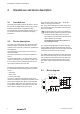
Intended use and device description 2 Intended use and device description 2.1 Intended use The safety relay SCS 24VDC P1SIL3ES LL serves the purpose of safety-related switch-on of process industry systems (ETS = energised to safe). The device fulfils the safety integrity level 3 (SIL 3) for low demand mode of operation according to EN 61508. 2.2 There are three status LEDs “RLY”, “DIAG” and “ERR” on the front of the device.
Notes on configuration 3 Notes on configuration 3.1 Low demand mode of operation The safety relay is used with a low demand rate (low demand mode) when the demand rate of the relay does not exceed 1x per year. The associated technical parameter is the value PFDavg that applies to the duration of the test interval Tproof. 3.2 Types of malfunctions A safe failure is not able to render a technical safety system dangerous or non-functional. The safety relay passes to a predefined safe state.
Commissioning and maintenance 4 Commissioning and maintenance The following operating instructions must be available for the safety relay. Designation: IS SCS 24VDC P1SIL3ES LL Order number: 2689760000 The safety relay must be checked for proper functioning prior to commissioning and after every change in wiring, see chapter 5.1 „Functional testing“. It contains notes, boundary conditions and limit values that must be factored into the installation and operation of the safety relay.
Proof test 5 Proof test The purpose of the proof test is to detect any dangerous faults that cannot be detected by means of self-diagnostics. Therefore, the functionality of the safety relay must be tested in appropriate intervals. The selection of the type and intervals of the tests is the responsibility of the operator. The test intervals are, among other factors, determined by the calculation of each individual safety circuit in a system (PFD values).
Proof test 5.
Proof test The following table describes the step-by-step functional test of the safety circuit (relays 1 to 3). SCS 24VDC P1SIL3ES LL (2633940000) Test step Uinput Uoutput S1 T1 T2 T3 LED ERR LED LED RLY DIAG V1 V2 A1 A2 V3 0V 0V 0 mA 0 mA 0V Check that all output contacts open when safety relay is not energised. Step 1 off 24 V open NC NC NC off off off Apply 24 V on connection terminal A1 and check that 24 V is present on connection terminal T1, T2 and T3 (steps 2, 3 , 4).
Technical safety values 6 Technical safety values Safety basic data Safety category SIL 3 Safety standard EN 61508 Device type A HFT 2 Tproof in years 12 The safety parameters can be found in the TÜV certificate with the registration number 44 207 13773719. The certificate is available for download at www.weidmueller.com.
www.weidmueller.com Weidmüller Interface GmbH & Co. KG Klingenbergstraße 26 32758 Detmold Germany T +49 5231 140 F +49 5231 14292083 www.weidmueller.