
User Documentation


Device description and application
1373930000/02/06-2017 7
2. Device description and application
2.1 General
Our SAFESERIES line of safety relays are used
for safety-related shutdowns (DTS = de-energized
to safe) of facilities in the process industry.
All products in this series comply with the require-
ments found in EN 61508, SIL 3 for “low demand
mode” and “high demand mode”. The “M” and
“M G3” types also feature a monitoring circuit for
receiving signals from the field. The “M G3” types
also feature a special coating over the electronics
that protects them from harsh industrial
conditions, as described in the standard
ISA S71.04-1985, Class G3.
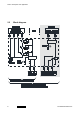
2.2 Design and function
Three relays are connected in parallel in the input
circuit (A1/A2). The relay’s output contacts
(terminals 13 and 15) are wired in series. Thus,
safety-related shutdowns are ensured even where
there is a welding contact. The output is protected
with a 5 A fuse against overloads and short
circuits. The output contacts (terminals 14 and 15)
are used when using external fuse protection or
when checking the fuse. It is also possible to
check the switching status of a relay in the safety
circuit by using the output (NC) contact at
terminal T.
The relay coils are energised when the nominal
voltage of 24 V DC is applied between the input
terminals A1 and A2.
The switch function is signalled with the “RELAY
OUTPUT” LED display.